MDE-3664B TRIND® Start-up, Service, and Parts Manual · June 2013 Page 8-11
Troubleshooting T20229-G1 PCB on Card Cage Assembly Testing and Troubleshooting
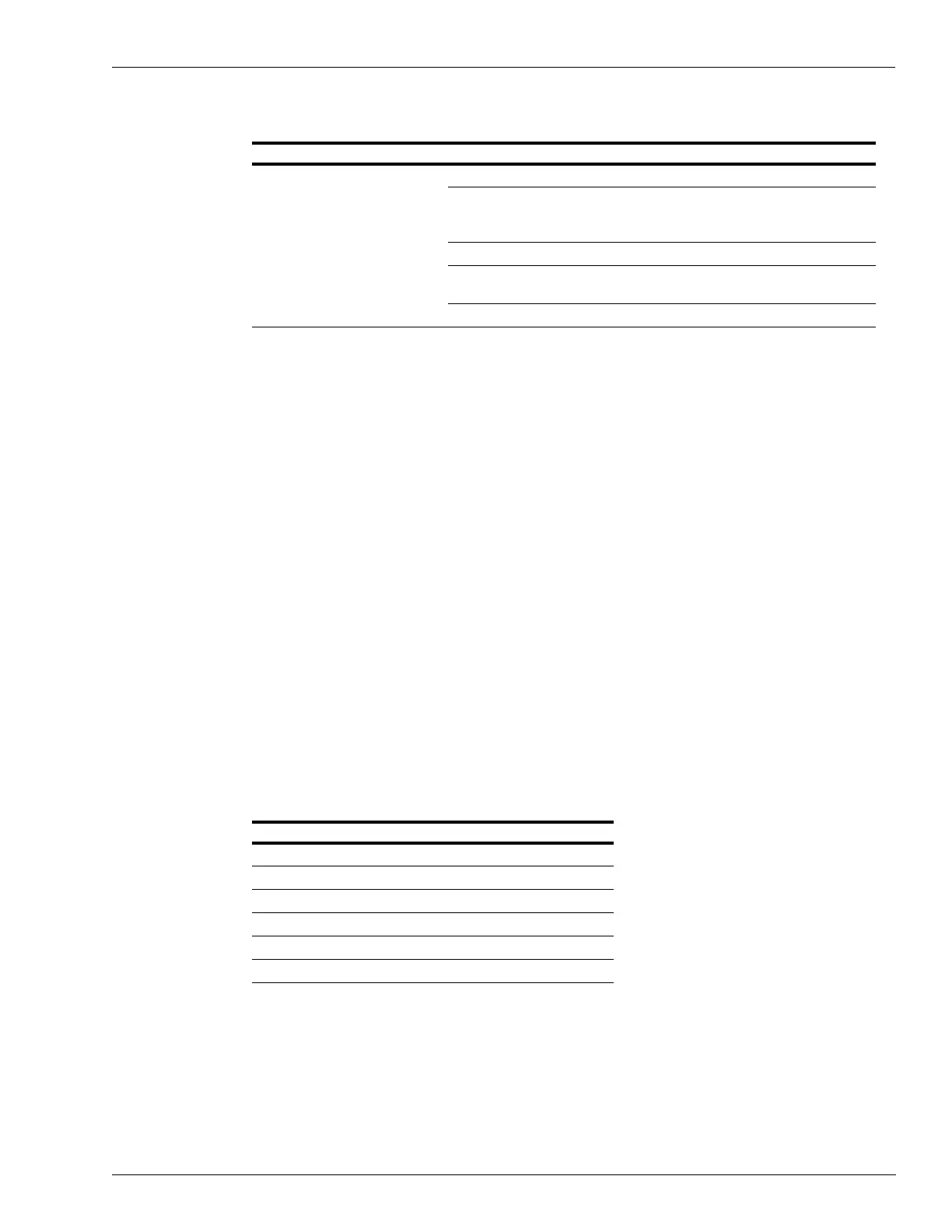
DCB (Q13563-01)
Normal Operation Abnormal Operation/Failure Cause/Action Required
• LED CR2 (+5 V) on solid.
• LED CR3 (+12 V) on solid.
• CR10 (RS-485 RX) and CR11
(RS-
485 TX)
pulsing
synchronously.
• CR5 (heartbeat) pulsing.
• CR6 (Read ANT) will light when
t
ag is r
ead.
CR10 and CR11 not pulsing. Check RS-485 serial connection (J4)*.
CR7 lit (Bezel I/O error). Will only light when a Light/Micro
Reader PCB has a communication
pr
oblem.
CR2/CR3 not lit. Check TI/RFID Power Supply Board.
CR6 not lighting. Refer to “Tuning Tool (Q13631-01 and
Q13631-02)” on page 5-6.
CR5 not pulsing. Replace DCB.
*This is ser
ial connection for DCB and Gateway Boards and means by which TRIND talks to G-SITE POS
sys
tem.
TI/RFID Power Supply (T20138-G1)
Power supply is gated, a current sensing circuit will turn off the “power rail” if a harmful
situation is detected. A problem on another board will cause a shut-off of power output from
the TI/RFID Power Supply PCB.
To troubleshoot TI/RFID Power Supply:
1 Verify the voltage output from TI/RFID (refer to “T20138 and T20314 Power Supply Boards”
on page 4-6).
Note: Voltages are bussed, meaning that output can be checked at a single point on the board.
2 If voltage not present or reduced, verify that TI/RFID Power Supply is receiving 60 V from
Transformer at P174.
3 If 60 V is present, power down TRIND, remove connector at P173, power up, and recheck
voltage with connector still off.
4 If voltage is normal, problem is on DCB (see following table). If problem persists, reconnect
P173, and repeat step 3 for each of the following in sequence (except P173) or until problem
board is located:
Connector Problem Identified (if voltage returns to normal)
P173 DCB
P175 DCB
P176 Light/Micro Reader PCB Side B
P177 Light/Micro Reader PCB Side A
P178 Transmitter PCB
P179 Gateway PCB