MDE-3664B TRIND® Start-up, Service, and Parts Manual · June 2013 Page 4-31
TRIND Option Doors with Antennas Major Hardware Components
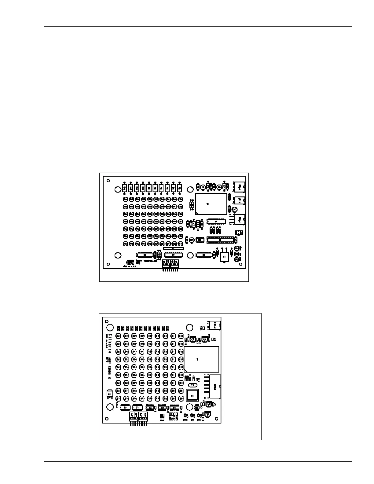
Light/Micro Reader PCB (T20446-G1, T20601-GX, M01580A001, and
M01580A002)
Note: T20446 replaced Light/Micro Reader PCB T20182-G1 and T20295-G1. M01580A001
and M01580A002 replaced Light/Micro Reader PCB T20601-G1 and G2.
The PCB is mounted on the right options door on The Advantage Series units or in an
enclos
ure mounted on the bezel for MPD
-
3 units. The PCB processes data received from the
hand-held transponder and provides tag read indicator lights for the TRIND system. The PCB
requires both 5 VDC and 22.5 VDC supplied at P182 plug. The PCB also provides hand-held
transmitter information to the DCB or Enhanced Gateway Board. In addition, the PCB
receives information regarding light control from the DCB. These activities are also done
through P182 plug.
Figure 4-32: T20446-G1 Light/Micro Reader PCB
Note: Used with T20229 Card Cage in C00011-001 Kit.
Figure 4-33: T20601-G1 Light/Micro Reader PCB
Note: Used with T20606-GX Card Cage in C00011-002 Kit and above.