Testing and Troubleshooting Status Indicators
Page 8-2 MDE-3664B TRIND® Start-up, Service, and Parts Manual · June 2013
The Gateway Board will have the following indicator characteristics when operating properly:
• +5 VDC LED on solid (CR8).
• Blinking Central Processing Unit (CPU) LED (CR6). A dimly lit LED can
also indicate
proper operation because the blink rate becomes so fast that the LED appears dimmer than
the +5 VDC LED (CR8).
• Rapidly Blinking CRIND A and B LEDs. Side A is CR4 (TX), CR5 (RX), Side B is CR9
(TX). These LEDs indicate good communic
ation with the CRIND. They mimic the LEDs
on the series of T17764 CRIND Boards. The Encore 500 Series CRIND node has two
TRIND LEDs, D12 and D13, present in board under the TRIND connector.
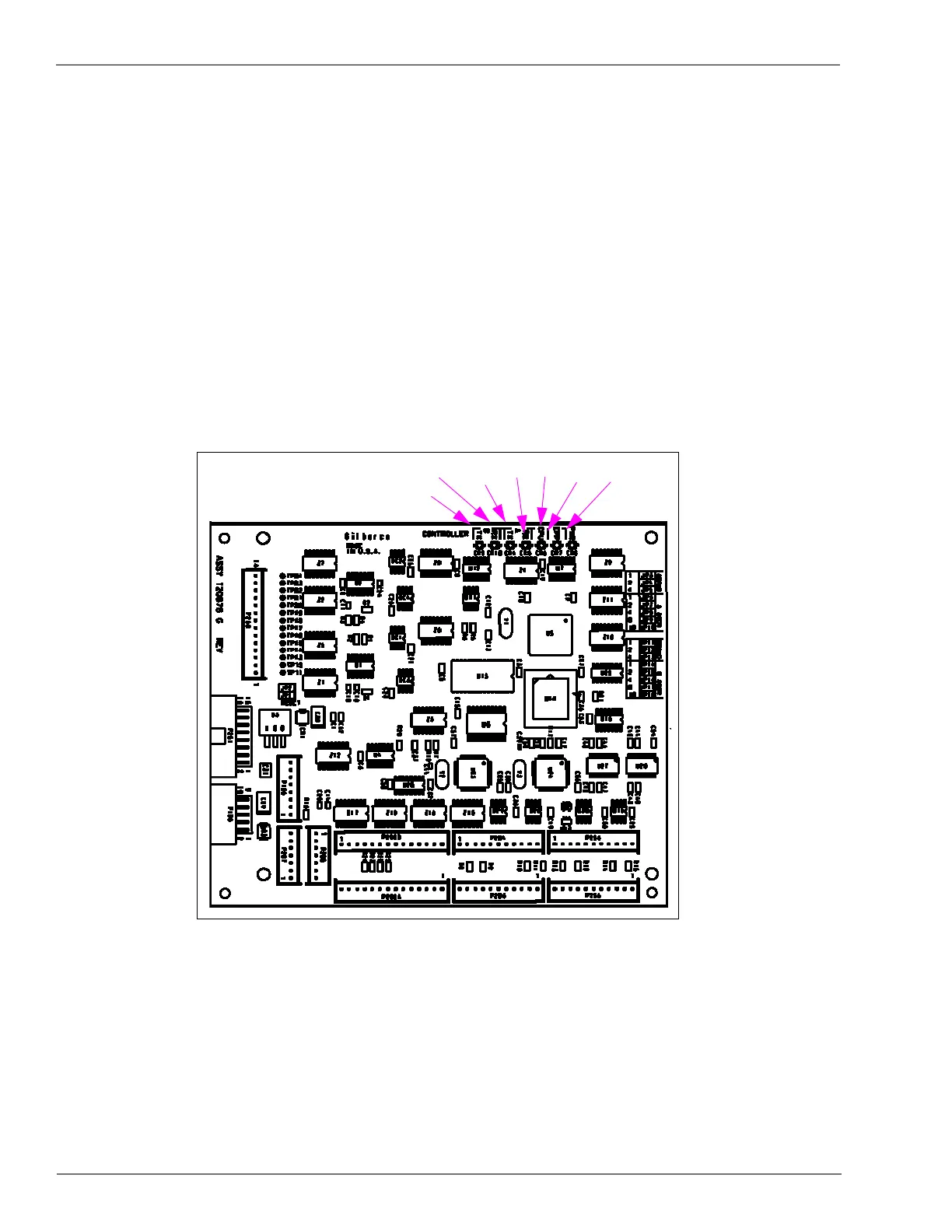
Enhanced Gateway Board (T20678)
Figure 8-2 shows Status indicators for the Enhanced Gateway Board.
Figure 8-2: Enhanced Gateway Board