MDE-3664B TRIND® Start-up, Service, and Parts Manual · June 2013 Page 5-3
Standalone Jumper Cables System Accessories
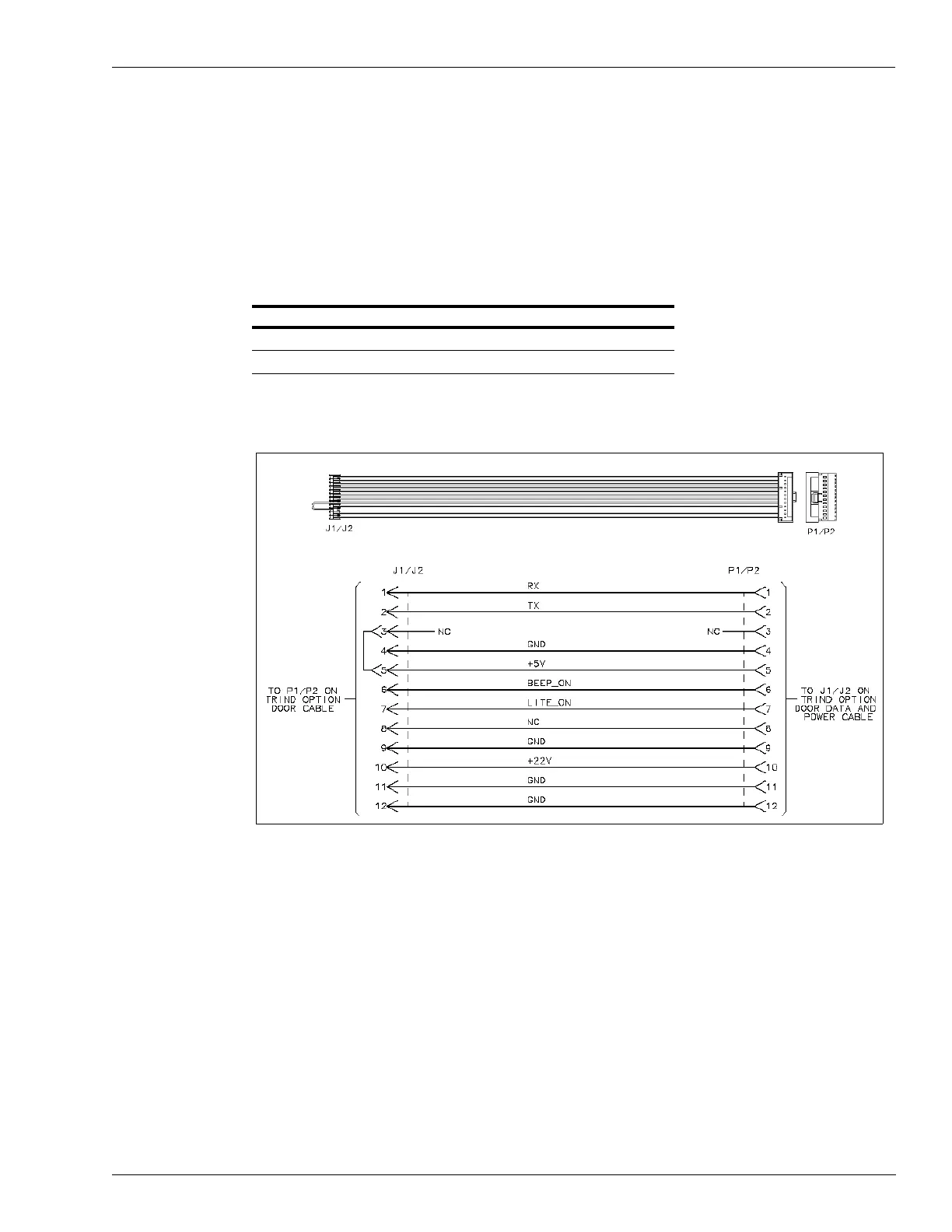
Standalone Jumper Cable (R20602-G2) for Enhanced Gateway
This cable is used for installation or troubleshooting, and for placing a unit in the “standalone”
mode. The hand-held key tag units contain the T20606-G3 Card Cage Assembly and the
Enhanced Gateway PCB (T20678-G1). After powering down unit, the P1 end of the
M00507A001 Cable coming out of the Card Cage on Side A is disconnected. The P1/P2 end
of the Standalone Jumper Cable is connected to the P1 end of the M00507A001 Cable, and the
J1/J2 end of the Standalone Jumper Cable is conn
ected
to the J1/J2 end of the R20773-02
Cable that is connected to the Light Board Assembly (M01218A001). TRIND is in the
“standalone” mode when power is restored to the unit.
Connector on R20602-G2 Connects To On
P1/P2 P1 M00507A001 Cable (Side A)
J1/J2 J1/J2 R20773-G2 Cable
Figure 5-3: R20602-G2 Standalone Jumper Cable and Wiring Diagram