MDE-3664B TRIND® Start-up, Service, and Parts Manual · June 2013 Page 8-1
Status Indicators Testing and Troubleshooting
8 – Testing and Troubleshooting
Following sections provide testing and troubleshooting information for the TRIND system.
The status indicator section describes the characteristics of key TRIND indicators when the
TRIND system is operating properly. The troubleshooting flow chart section provides a
graphical guide to assist in troubleshooting the TRIND system.
Note: The majority of failures that occur are attributed to insuff
icient initial setup detail.
Proper Gateway Board addressing and accurate cable connections are crucial to the
effective operation of the TRIND system.
Status Indicators
Following sections describe the display characteristics of key indicators when the TRIND
system is functioning properly.
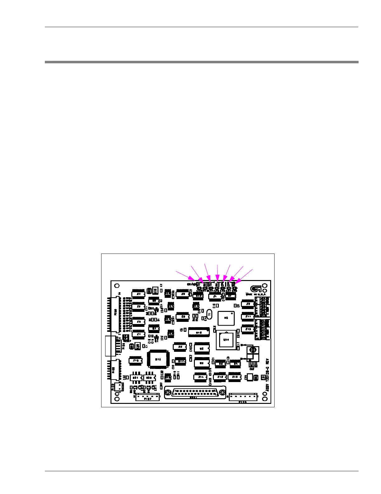
Gateway Board (T20128)
Figure 8-1 shows Status indicators for the Gateway Board.
Figure 8-1: Gateway Board