Major Hardware Components TRIND Option Doors with Antennas
Page 4-32 MDE-3664B TRIND® Start-up, Service, and Parts Manual · June 2013
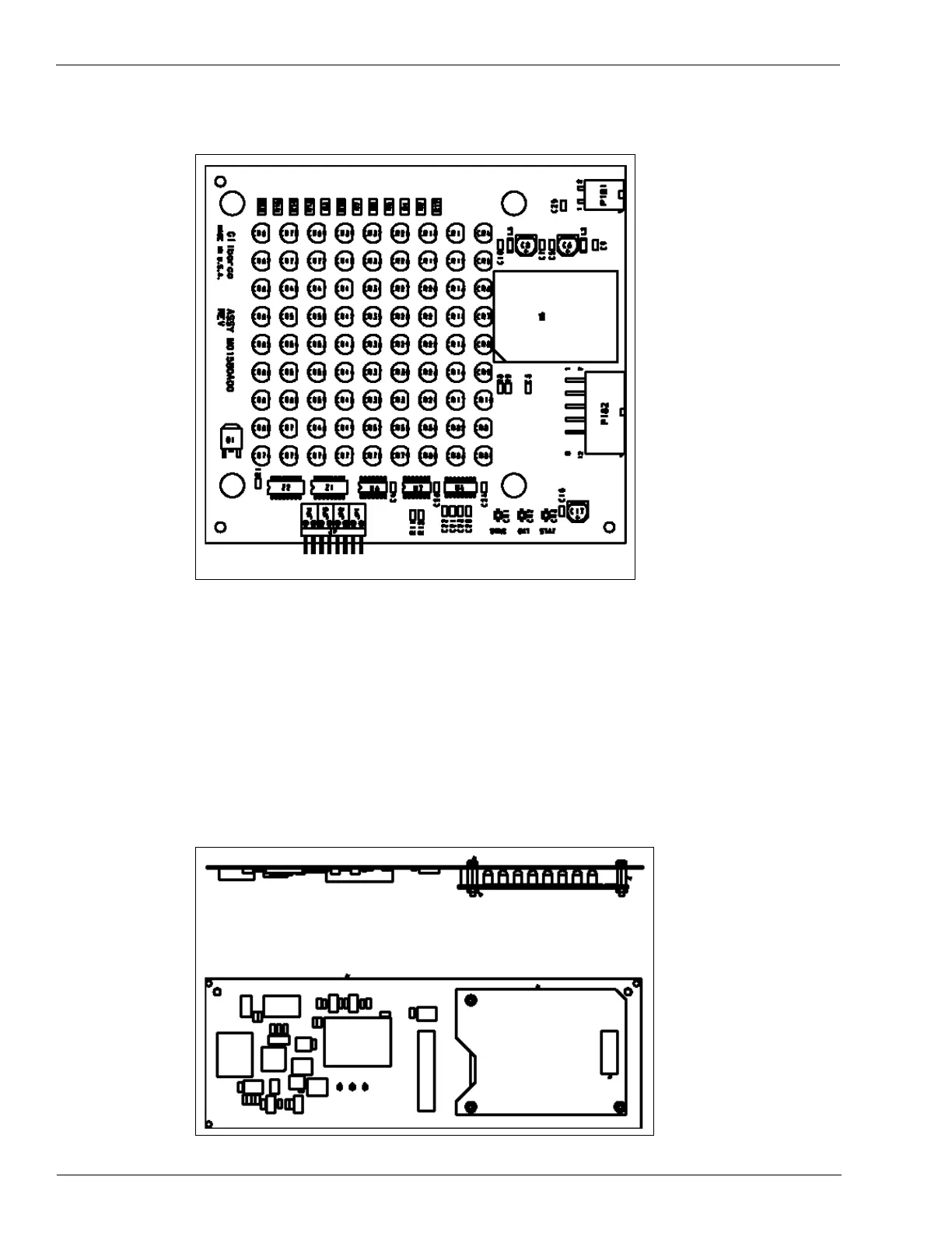
Figure 4-34: M01580A00X Light/Micro Reader PCB
Note: Used with T20606-GX Card Cage in C00011-002 Kit and above.
M01218A001 and M01218A002 Light/Micro Reader PCB
Mounted on the CIM Door on Encore and Eclipse units, this PCB processes information
received from hand-held transponder (only), as well as provides indicator lights for the
TRIND system. The PCB requires both 5 VDC and 22.5 VDC supplied at P182 plug. The PCB
provides transmitter activity data to the DCB, and receives light control information from the
DCB. These activities are done through P182 plug. The antenna is integrated into this
assembly.
Figure 4-35: M01218A00X Light/Micro Reader PCB