MDE-3664B TRIND® Start-up, Service, and Parts Manual · June 2013 Page 4-7
Card Cage Assemblies Major Hardware Components
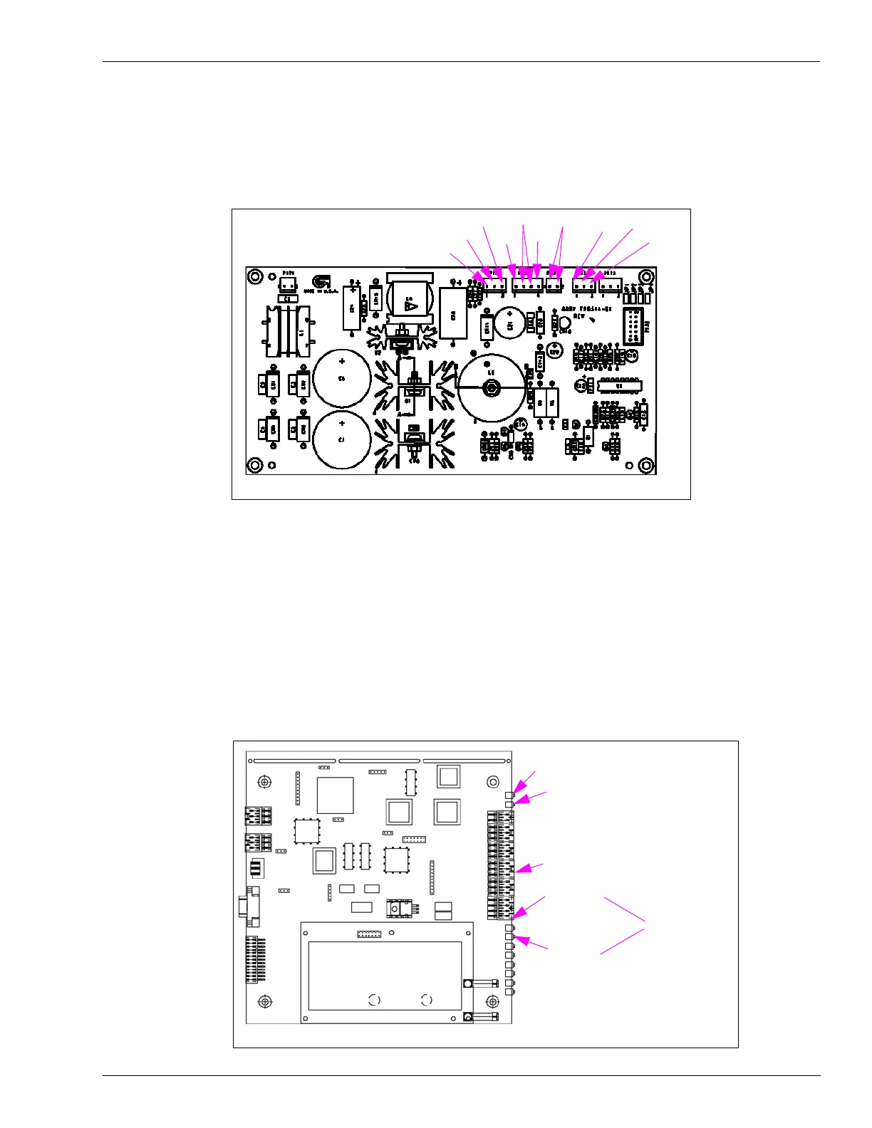
T20314 Power Supply Board
This board must be used in conjunction with the R20719 Transformer.
Figure 4-7: T20314 Power Supply Board
5 V
GND
22 V
GND GND
5 V
22 V
GND
Note: P176, P177, and P178 are identical.
22 V
5 V
Q13563 Data Control Boards
Q13563-01 and Q13563-02 Data Control Boards are used in T20229-G1 Full System Card
Cage assembly. The Q13563-04 Board is used in T20606-G2 Full System Card Cage
assembly. These DCBs handle tag reader control and pass the system status, and tag data up to
the Gateway Board. The earlier versions (-01, -02) of this board made use of jump jacks on the
Power Supply Board for dither sync addressing, subsequent versions (-04 and above) contain
Dual Inline Package (DIP) switches for this site-specific addressing.
Figure 4-8: Q13563-01 and Q13563-02 DCBs
CR5 - pulsing (heartbeat)
CR11 - RS485 - TX
CR10 - RS485 - RX
Note: In normal operation CR10-RS485-RX and CR11 - RS485 - TX will be in sync.
CR3 - 12 V
CR2 - 5 V
On Continuously