MDE-3664B TRIND® Start-up, Service, and Parts Manual · June 2013 Page 3-3
Full Systems Systems Overview
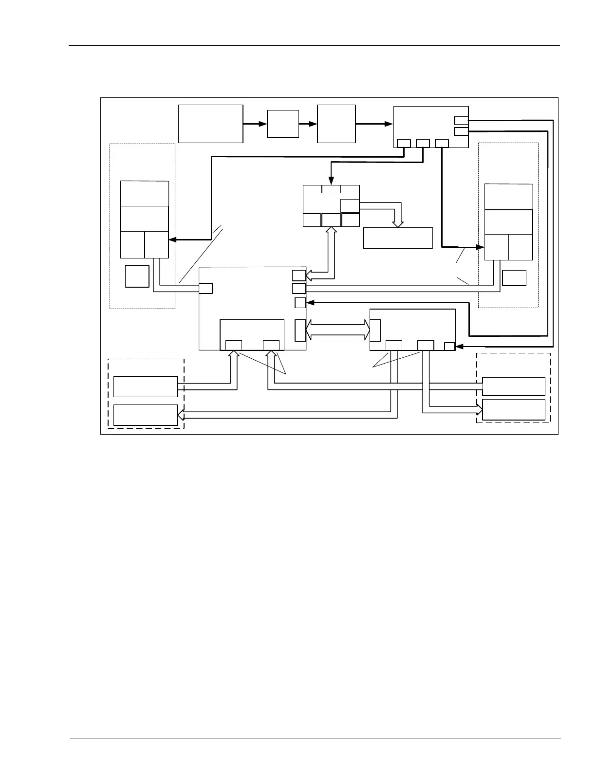
Figure 3-3: Encore Full System Block Diagram
Overhead Antenna Assembly
Side A
LF Transmitter (134kHz Intentional
UHF Receiver Module
RI-RFM-HRUA
902 - 928 MHz
115 VAC
(FROM Dispenser
AC POWER
DISTRIBUTION)
RS-232
(Dispenser Electronics)
P187
P250
P185
22VDC, 5VDC,
GND
5VDC,
GND
J2A J2B
LF Transmit Antenna
UHF Receive Antenna
Overhead Antenna Assembly
on Dispenser Bezel Face
(Side A)
POWER REGULATING
P177P179P176
P175
P178
Light Board Assembly
M01218A00X
on Dispenser Bezel Face
(Side A)
Control Circuit
P182
RS-232, Digital
Control and Light
Control Circuit
J1A
J3A
M00878A001
M00878A001
M00878A001
Cable
Cable
Cable
Tuner Board T20579
Q13851-01
Q13851-01
WO3889
WO3889
When overhead antennas are not part of
the product, Dummy Load R20526-G1
plugs into JA and JB. J2A and J2B are
left unconnected.
Q13563-02 or -04
5 MHz (UHF Clock - selected
10 MHz (Local Clock - not
selected for this application)
Power Supply
AC Power
EMC Filter
Q10895-01
Micro-Reader
Q13551-01
(134 KHz
Intentional)
Micro-Reader
Q13551-01
(134 KHz
Intentional)
M00878A001
Cable
Antenna
(on board
Encore
keytag
Antenna
(on board