22 / 80
33028_mc_28_Teil2_jh
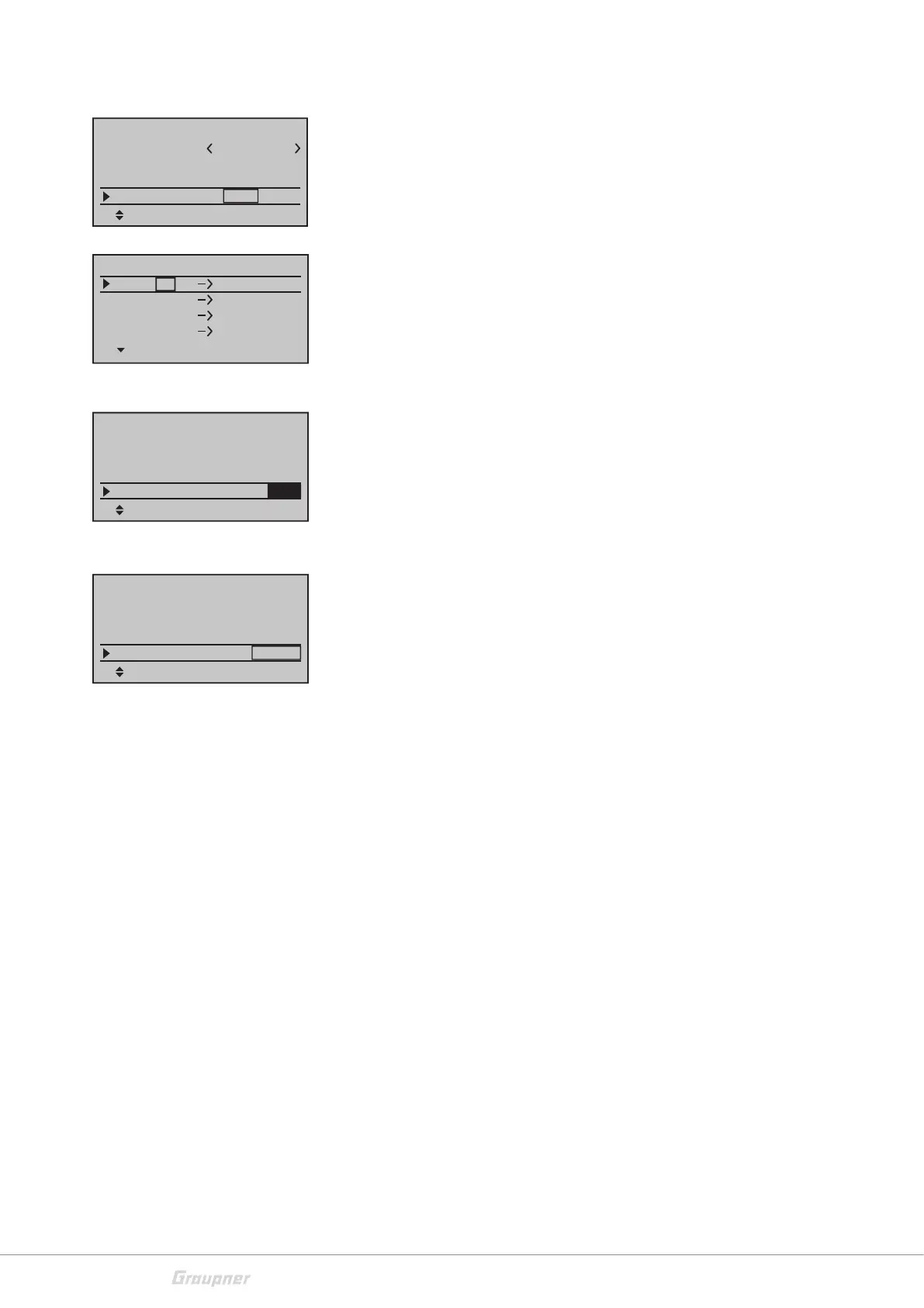
Receiver output
This function (Channel Mapping) is available as soon as in the line
"Module" is bound at least one receiver. Here you can split the con-
trol channels of the transmitter to the bound receivers. You can also
select freely the channel order within the receiver. In this way the
control channels coming from the transmitter will be assigned to a
free selectable output of the receiver.
Use the selection buttons to move to the receiver field that you want
to edit. Select the input that you want to assign to another output.
Tap on the SET button. Set the desired channel. Confirm the selec-
tion by pushing the SET button.
RF module
In this menu line the RF module of the transmitter is switched man-
ually on and off. This line is only available if a receiver is bound.
Range test
The integrated range test reduces the transmitter output so that you
can perform a function test at a limited distance.
Perform the range test before each operation and simulate all servo
movements which are part of the operation. In order to guarantee a
safe model operation, the range must always be at least 50 m on the
ground.
Place the model on a flat surface (cement, mowed lawn or ground)
so that the receiver antennas are at least 15 cm above the ground.
If necessary, place a support underneath the model during the test.
Hold the transmitter at hip level at a slight distance from your body.
Keep the surface of the patch antenna of the transmitter in direction
of the model.
Start the range test by pushing the SET button. The time display "99
sec" will start the countdown. You will hear two acoustic signals each
two seconds, in the last five seconds the acoustic signals will be 3
each second.
During this time, move away from the model, and also move
the transmitter's control sticks. Let the control movements be
observed by a second person.
If within a distance of about 50 m there is no interference in the con-
trol movements of the model, then the range test can be considered
as successful. After the end of the 99 seconds
the transmitter switches again to full transmission power and the
green LED on the right of the main switch lights again permanently.
If the range test has not been successful, verify the following condi-
tions:
Mod. name
Stick mode
1
bind
Base setup model
bind
SET
GRAUBELE
SET
Rcv Ch Map R12
R08
Module
HoTT
Receiver CH – BIND1
In Ch 1
Out Ch 1
In Ch 2
Out Ch 2
In Ch 3
Out Ch 3
In Ch 4 Out Ch 4
bind
Base setup model
SEL
Rcv Ch Map
R08
RF transmit
Stick mode
1
ON
bind
R12
Module
HoTT
bind
Base setup model
SEL
Rcv Ch Map
R08
RF transmit ON
RF Range Test 99sec
bind
R12
Module
HoTT