35 / 80
33028_mc_28_Teil2_jh
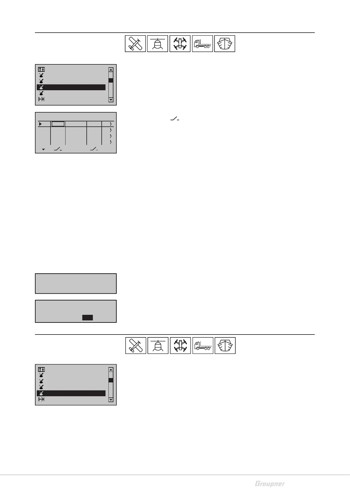
Logical switch
Through this function two switches, controls and/or logical switches
or the favorite combination of them, can be interconnected. It is
realized through a "AND" or "OR" switch. You can program a total of
eight logical switches ("L1 ... L8") in each model memory. The result
of such a logical switch function can be used as alternative switch
function.
In the column “
“ you can assign both switches that have to be
connected. In the column SEL you can select the connection "AND"
or "OR". In the column on the right side is represented the state of
the logical switch.
Function of the connection
Function "AND": A logical switch is then "closed", when both switches
are "closed".
Function "OR": A logical switch is "closed" when one of both assigned
switches is closed.
Programming the logical switch step-by-step:
• Select the line of the desired logical switch
• Assigning the switch
• Select the connection type ("AND", "OR")
• Select the second switch
If you assign a programmed logical switch, you have the possibility
to select the switch in the normal (L1 - L8) or inverted (L1i - L8i) switch
function. Push then again the SET button and scroll down through
the selection keys to the input window.
Announce
Through this function you can assign 20 announces to a switch. A
selection of those announces is included in the transmitter memory.
You can also save your own announces as .wav or .mp3 files. There-
fore you need the Firmware_Upgrade_grStudio
If the function has to be assigned specifically to the phase, the
related phase must be active. In the second line from the bottom of
the display will be shown the phase name.
Switch display
Control switch
Channel 1 curve
Phase settings
Logical switch
Announce
AND
AND
AND
L1
L2
L3
–––
L4
Logical switch
AND
–––
–––
–––
SEL
L1
L2
L3
L4
–––
–––
–––
–––
Move desired switch
to ON position
(ext. switch: SET)
Control/Logic/fix sw
C4i C5i C6i C7i
C8i L1i L2i L4i
C3i
L3i
Switch display
Control switch
Channel 1 curve
Phase settings
Logical switch
Announce