62 / 80
33028_mc_28_Teil2_jh
4. In the left column, select the channel to be edited first, then
proceed with the other channels the same way
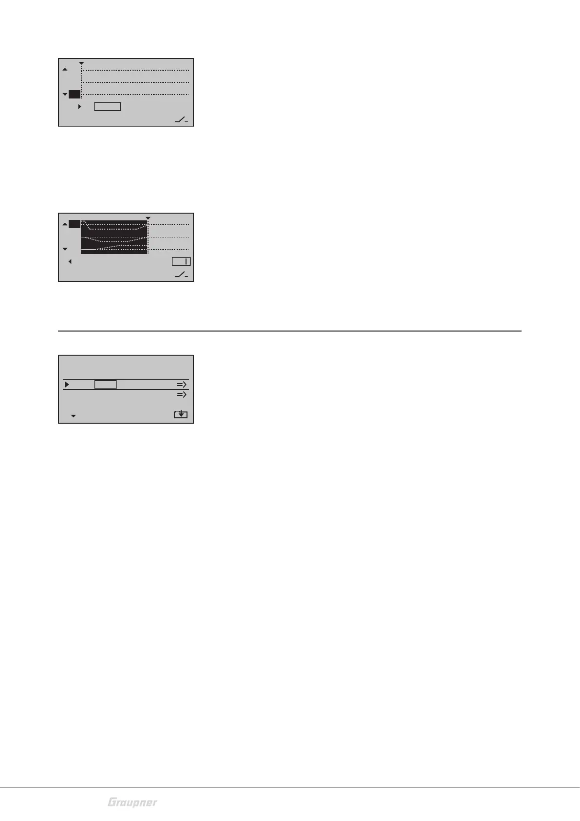
5. Sequence 0
u: Set the initial position in the value field through
"POS".
6. In the value field of the "Time" column, use the selection keys
t u (left) to set the duration of the first sequence.
7. Sequence 1 … max. 9 - The next sequence is selectable
when a time has been set. Select the next frequency and repeat the
steps described above for each additional sequence until you reach
the target positions of your servos.
8. Switch assignation - Finally assign to the just completed
sequence an activation switch through which you can switch between
the output and the target positions of the servos. As soon as the
switch is closed, the movement of the servos can be traced in the
graph. The control curves are highlighted according to the given time
windows. All the movements will move reversed when the switch is
"opened" again.
Multichannel
In this menu you can use two control channels for four or eight spe-
cial functions.
For this you need optional accessories for the receiver:
NAUTIC Expert switch module No. 4159 or 3972
This NAUTIC Expert switch module extends a servo function to 16
switch functions.
NAUTIC Multi-prop Mini Decoder No. 3973
The 1/4 K-NAUTIC multi-prop mini decoder extends a proportional
function to four proportional functions.
Light module No. 2381
Module for realistic switching of light signals for ships, trucks and air-
planes.
Sound switch for surface models No. 2382.F
Start, stop and additional noises as well as vehicle-type signals
Sound switch for ship models No. 2382.S
Start, stop and additional noises as well as ship-type signals
You can find further information on www.graupner.de.
Alternatively, contact your dealer or Graupner Service Center.
TIME
POSST
11
12
8
0%
10
0.0s
2
MC1
MC2
Multichannel
SET
SEL
OFF
OFF
MUL4C
MUL4C
C6
C6
SEL
TIME
POSST
11
0
0% –––
0.1s
10
12
 Loading...


