34 / 80
33028_mc_28_Teil2_jh
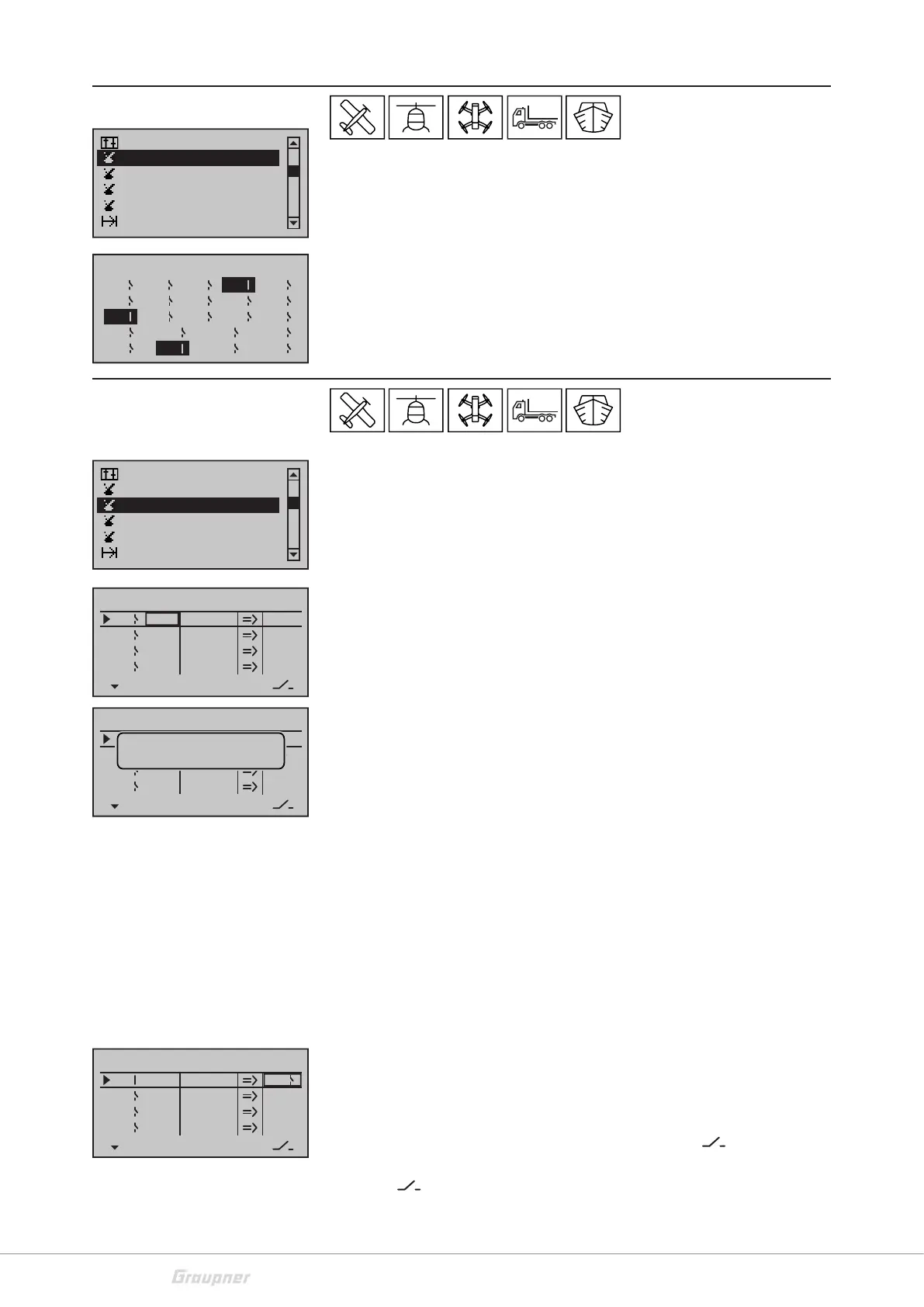
Switch display
The switch display is a mere display, it is a check function of the
switches and control switch in the transmitter.
Active switches are highlighted. On the right near the switch number
the switch position is displayed with a switch-symbol.
Control switch
In this menu a switch function is paired to the control travel of a pro-
portional control.
Assigning the control switch:
• Select the line of the desired control switch
• Activate the column "SEL" through the SET button
• Actuate the desired control, the abbreviation of the control will
appear
Deleting the control switch:
• Use the SET button to select the desired field
• Tap on the selection buttons "left/right" or "up/down" at the
same time
Setting the switching point
• Select the STO column,
• move the control to the desired position
• Save the position through the SET button
Setting the switch direction:
• Select the column SEL, change the switch direction through the
SET button
Combining the control switch
A control switch can be controlled by another switch, so that in spe-
cific situations the function to be switched can be switched, inde-
pendently from the control position and from the control switch
position. Therefore assign a switch in the column "
". You can also
combine 2 control switches. Therefore select a control switch in the
column “
“
Switch display
Control switch
Channel 1 curve
Phase settings
Logical switch
Announce
Schalter
C1
C3 C4
51 2 3
6
7 8 9 10
12 13 14 1511
4
C2
C5
C7 C8
C6
Switch display
Control switch
Channel 1 curve
Phase settings
Logical switch
Announce
SEL
+75%
0%
0%
G1
G2
C3
–––
C4
Control switch
Gb1
Gb1
–75%
STO
–––
–––
–––
Move desired
control adj.
SEL
SEL
0%
0%
0%
C1
C2
C3
–––
C4
Control switch
SD2 +85%
STO
10
–––
–––
SEL
SEL
0%
0%
0%
C1
C2
C3
–––
C4
Control switch
Gb1
Gb1
0%
STO
–––
–––
–––
SEL