72 / 80
33028_mc_28_Teil2_jh
5. Phase assignation menu:
• Switching off the autorotation switch
• Select the switch for the normal flight phase and switch it off in
the correct position.
• Select combination C and press the SET key
• Actuate the selected flight phase switch.
• Switch to test whether the switch between the flight phase Nor-
mal and Acro 3D is correct.
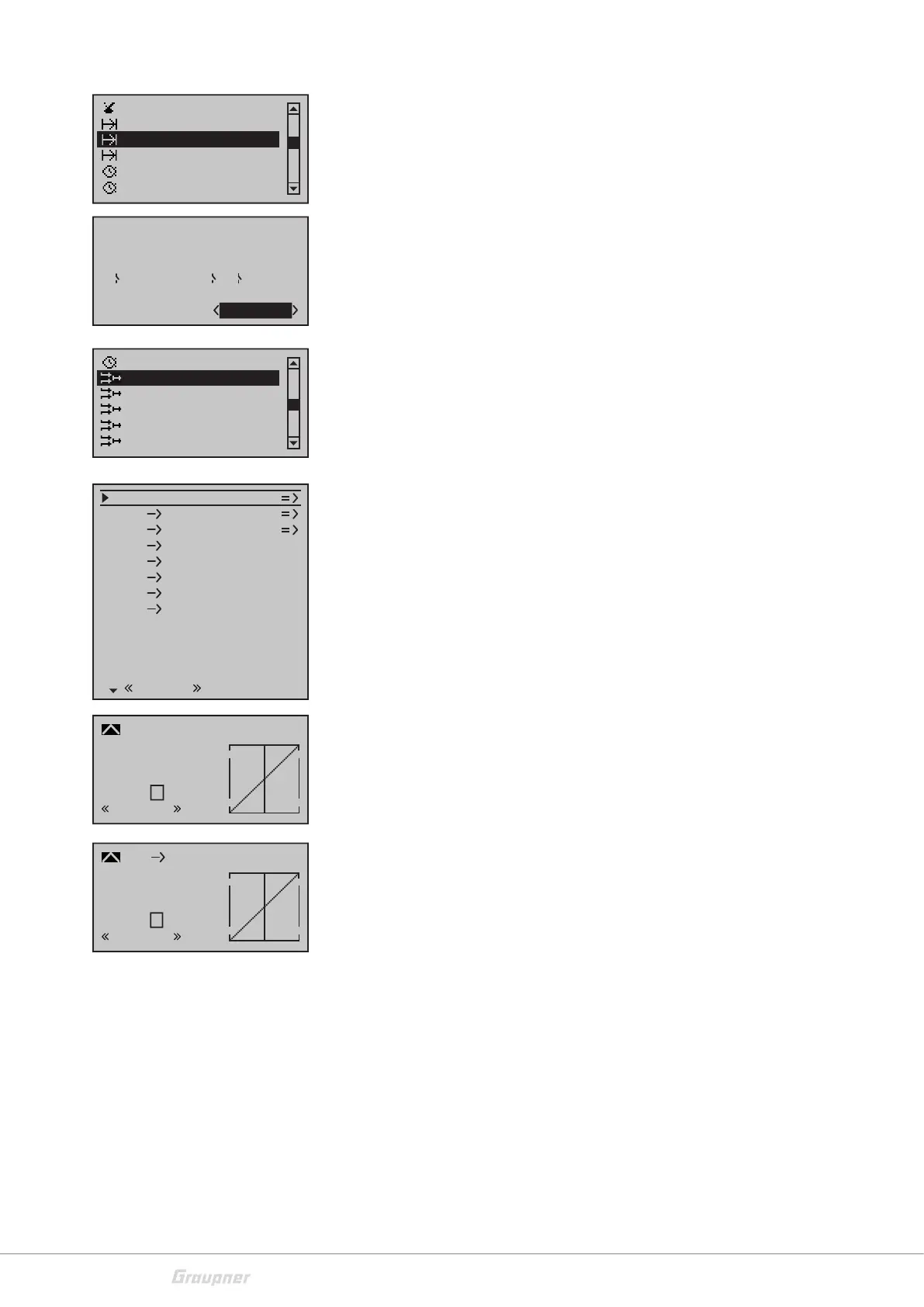
6. Helicopter mixer menu:
• Activate the autorotation switch
• Throttle position AR -100% for electric motor, -90% for IC engine.
• Deactivate the autorotation switch.
• Select CH1->Throttle
• Pre-programmed diagonal throttle curve can be used for com-
bustion engines and electric motors with controllers without
Govenor mode. Pitch stick = Throttle stick
• For speed controllers with Govenor mode a horizontal gas line
must be programmed as follows:
Here, in the "lower" normal flight phase, a lower throttle / speed
is selected than in the second Acro 3D flight phase, e.g. 40%. To
do so, move the pitch stick to min. and tap the SET button. With
the arrow up, the beginning of the curve can now be set to e.g.
40%. Then deselect this point of the curve with the SET key and
set the pitch stick to max. Tap the SET button again and lower the
rear point to 40% to create a horizontal throttle line. Then dese-
lect with the SET button.
• Now use the flight phase switch to switch to Acro 3D. Here, as
described above, a higher throttle line / speed can be pro-
grammed, e.g. 65% throttle.
• Afterwards you have now programmed 3 speeds / flight phases
for the Govenor:
• Autorotation for motor off
• Normal flight phase with 40% throttle
• Acro 3D flight phase with 65% throttle
• If a flybarless system is used in which the control travel needs to
be calibrated, it is advantageous to set up this flybarless system
before setting the throttle curves. Thus, the preprogrammed
diagonal throttle curve of channel 6 can be calibrated more eas-
ily.
Phase assignment
A B
C D E F
2
6
5
1 Normal
prior
combi
Phase settings
Non-delayed chan
Announce
Timer (general)
Phase timers
Phase assignment
C1
C1
Pitch
Throttle
Tail
Tail
0%
Roll 0%
Throttle
Roll
Throttle
Tail
Nick
Nick
Throttle
Tail
Swash rotation
Swash limiter
0%
0%
0%
0°
OFF
Normal
Gyro suppress
0%
Gyro gain
0%
SEL
Free mixers
MIX active/phase
Phase timers
Helicopter mixer
MIX-only channel
Swashplate mixer
Input
Output
Point
?
0%
0%
0%
Pitch
Normal
Curve
off
+50%
+50%
+50%
C1
Throttle
Input
Output
Point
Normal
Curve
off
?