23 / 80
33028_mc_28_Teil2_jh
Is the power supply of the receiver OK?
Is the position of the receiver antennas correct?
Are there any interference from electronic component in the
model?
If you have verified these conditions and against it you coul not per-
form a successful range test, then please contact ou Customer Ser-
vice (see section "Service Center").
DSC port
This selection influences the number of control channels available at
the DSC port. The selection means:
PPM10 = Channel 1 - 5
PPM16 = Channel 1 - 8
PPM18 = Channel 1 - 9
PPM24 = Channel 1 - 12
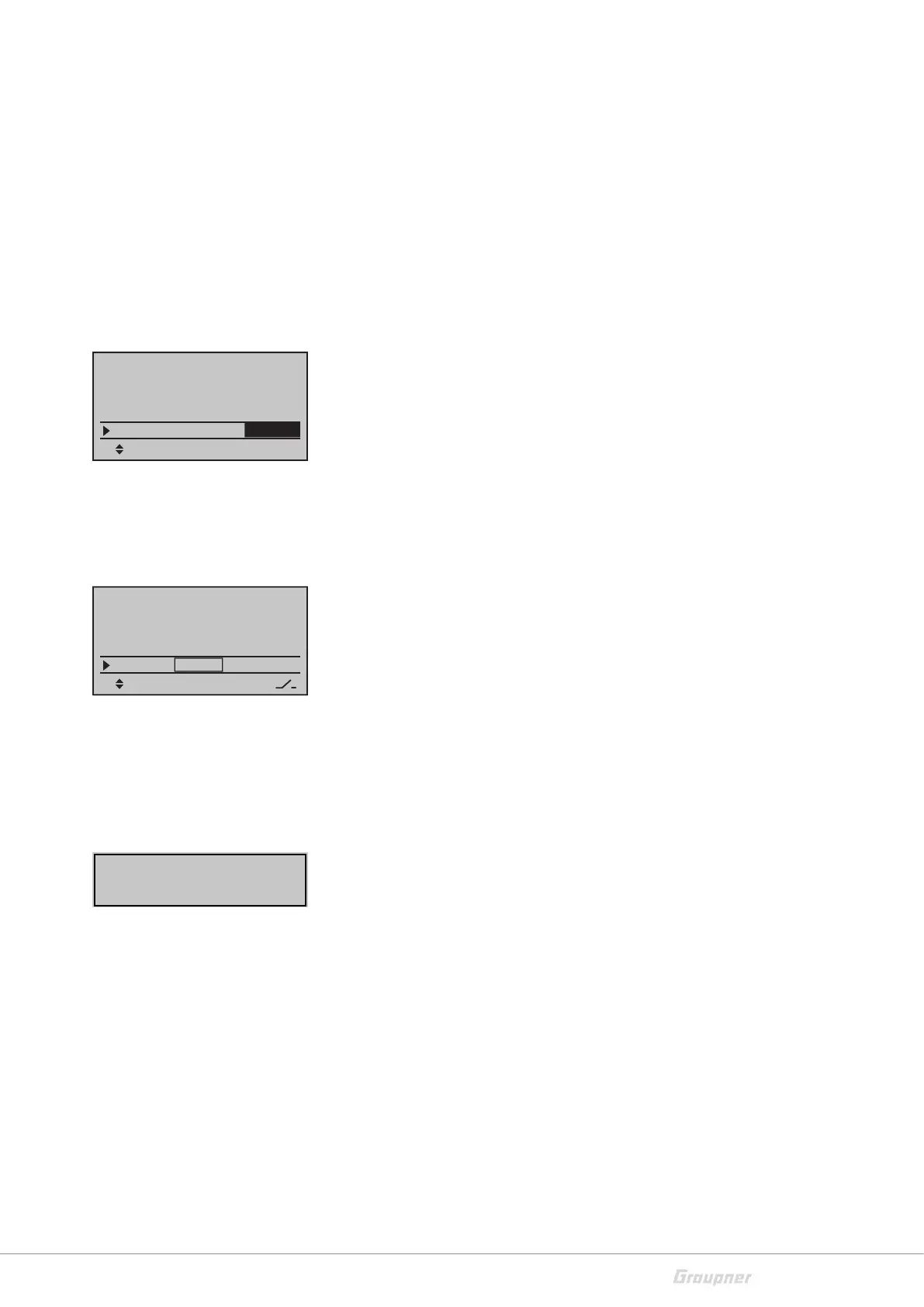
Throttle Cut
This function is only available if in the "Model type" menu you have
set "forward" or "backward" in the Motor to CH1 option.
With this function the throttle channel (CH1) can be switched and
hold in a specific position (-100%) through a switch. In this position
it is then not possible that the motor starts accidentally, no matters
in which position the throttle stick is.
In the left column you can set the position in which the throttle chan-
nel (CH1) will be switched. In the third column you can set the switch
threshold. To do that you have to move the stick to the desired posi-
tion and tap on the SET button. In this way the switch range will be
set.
In the right column you can assign the desired switch. Proceed as fol-
lows:
Tap on the SET button in the "Thr.cut" line.
Move the desired switch to the position in which the motor will
be switched off. Combinations with logical switches are also pos-
sible.
Base setup model
SEL
Rcv Ch Map R12
R08
RF transmit ON
RF Tange Test 99sec
DSC Output PPM10
Base setup model
SEL
RF transmit ON
RF Range Test 99sec
DSC Output PPM10
–––
cut off +150%–100%
STO
Move desired switch
to ON position
(ext. switch: SET)