60 / 80
33028_mc_28_Teil2_jh
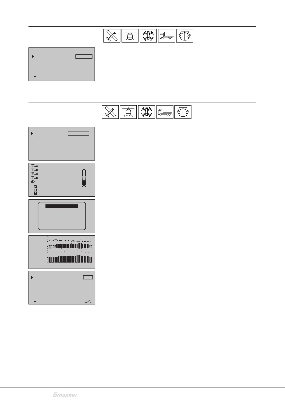
Trim memory
Storage of the actual trim position
In the left column (POS) is shown the actual value of the trim. If you
tap now the SET button, the trim value is transferred to the memory.
The trim value is now displayed in the "SET" column on the right side.
The bar display in the main display shows again the center position.
If you want to delete the stored trim value, tap the selection keys
t
u
or on the selected line.
Telemetry
Through the telemetry menu, you can perform receiver settings in
real time. Displays and settings of optionally connected telemetry
sensors can be retrieved and programmed. The connection to the
receiver is maintained by the feedback channel of the HoTT receiver.
TEL.RECEI. - Here you can set from which receiver the telemetry
data are to be processed and which settings in the following menu
item are possible.
SETTINGS & DATAVIEW - If you select this item, you will open the
menus for settings of the receiver or the sensors connected. Select
the desired sensor or module through the selection keys . (See
the manual of the sensor or of the module)
SENSOR: List of the sensors connected and detected (only display,
no manual selection possible)
DISPLAY RF STATUS - Top row: Level of channels 1 … 75 coming
from the receiver of the 2.4 GHz band in dBm to the transmitter. Bot-
tom row: Level of channels 1 … 75 coming from the transmitter of
the 2.4 GHz band in dBm to the receiver.
SELECT ANNOUNCE - In the first line, you can assign a switch and
set the repetition time to start the voice output. In the next line
"NEXT ANNOUNCE" you can assign a switch to switch the announce-
ments through. In the "VARIO" line, you can assign a separate switch
for the vario signals and select whether the sounds are to come
automatically (AUTO) or from a specific sensor (GPS, EAM, GAM).
Tap the SET button in the "TRANSMITTER, RECEIVER" line. In the list
that is now displayed, set which messages should be active by the
transmitter or receiver.
RX DATA - Here you can set how the transmitter responds to the
receiver's back channel (telemetry transmission). Use this function
if the back channel of the receiver is influenced by the back channel
of another receiver.
In the "ON" position the telemetry signals are processed continu-
ously. In the "1" position, the telemetry signals are processed with a
slight delay; the telemetry signals are processed in a very delayed
manner in position "10".
Trim memory
AILE
ELEV
RUDD
0% 0%
0%
0%
0%
POS SET
CH1 0% 0%
0%
Telemetry
SETTING & DATA VIEW
SENSOR
RF STATUS VIEW
VOICE TRIGGER
TEL.RCV
BIND. 1
RX DATA ON
ALARM SETTING
RX–S QUA: 100%
RX–S ST : 100%
TX–dBm: 33dBm
RX–dBm: 33dBm
RX–SPG.:4.8 TMP
V–PACK: 10ms
CH OUTPUT TYPE:ONCE
GENERAL MODULE
ELECTRIC AIR.MOD
VARIO MODULE
GPS
RECEIVER
ESC
RX–S QUA: 100%
RX–S ST.: 100%
TX–dBm: –33dBm
RX–dBm: –33dBm
RX–SPG.:4.8V TMP
V–PACK: 10ms
CH OUTPUT TYPE:ONCE
M–RX V :4.6V +22°C
R100%
T –40
E 10
R –51
4.8Vc
S 90%
4.8Vm 0123456789ABCDE
VOICE TRIGGER
REPEAT 10SEC
TRIG
TRANSMITTER
RECEIVER
–––
7
VARIO AUTO
–––