54 / 80
33028_mc_28_Teil2_jh
In a series switch of mixers, the mixed signal of the channel from the
upstream mixer is used as the input not the direct control signal of
the channel.
P : This option includes the trim values from the "Phase trim" menu
of the input channel as a function of the phase.
Notice
In the case of series switch, the mixing travel of the individual mixers
add together with simultaneous stick movement. As a result, the
servo or the servos may mechanically collide. To prevent the mechan-
ical collision, the "servo travel" must be reduced, a corresponding
"travel limit" in the "Servo adjustment" menu set, and / or the mix-
ing value should be reduced.
"From"
Channels 1 to 16, in case of model type "Airplane" the channels 1 to
4 are marked Thr (throttle), AILE (ailerons), ELE (elevator), RUDD
(rudder)
„S“ = Switch channel - the mixer input is assigned to a constant input
signal with the switch. The value of the signal is set in the display
page of the column "
".
"To"
In the input field of this column input the target of the mixer: the
mixer output to one of the control channels.
“ “
In this column assign a switch or control switch. This switch can acti-
vate or deactivate the mixer.
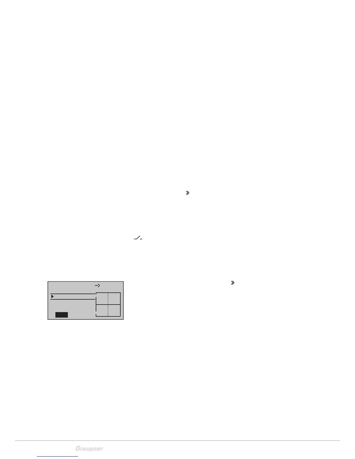
Setting the linear mixers M1 … M8
Open the display page in the column "
". Move the control of the
mixer input to move a vertical line in the graphic to the right of the
display. This line shows the position of the control. In the line
under "Mix input" set the travel of the mixer output. If "SYM" is
selected in the bottom line, the two values change symmetrically
(simultaneously). If you select "ASY" (asymmetric), you can change
the values separately. Each time the values are changed, the posi-
tion of the horizontal line changes. This line shows the travel of the
mixer output.
L.Mix1
0%
0%
0%
Offset
ASY
SYM
1
Mix input
3

 Loading...