55 / 80
33028_mc_28_Teil2_jh
Offset (mixer neutral point)
The dotted vertical line in the middle of the graphic indicates the
position of the mixer neutral point ("offset"). This is the point on the
control travel where the mixer does not affect the control channel.
By default this point is in the control center.
If you select the line under "Offset", the bottom line will show "STO"
and "SET".
Define the position for the offset with the control by selecting “STO”.
Select "SET" and the value is entered using the selection keys.
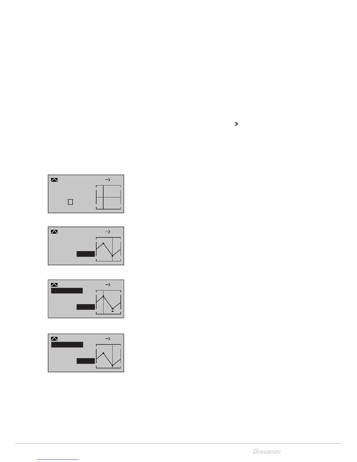
Setting the curve mixer C9 - C12
Open the display page in the column "
". Mixer guide lines can be
defined for the four curve mixers. These guide lines can be defined
by up to four freely adjustable points between the two endpoints "L"
(low = -100% control travel) and "H" (high = +100% control travel). In
the default settings of the program, 2 support points are already
defined, the endpoints "L" and "H".
Setting support points
Move the control of the mixer input to obtain a vertical line in the
graphic to the right of the display. This line shows the position of
the control. Move the line to the point to the desired support
point. Tap the SET button. A 1 and a percent display appear in the
"Point" line. If necessary, add the further three points.
Support points moving
Move the vertical line with the control of the mixer input to the sup-
port point "L, 1 to 4 or H". The support points will be changed. The
number and the current curve value of this point are displayed.
Activate the value field of the line Point. Then use the selection keys
to change the value to between -125% and +125%.
Trim point function
Alternatively, if the value field is active, select already set points by
ascending or descending with the selection keys. The selected point
is marked in the graphic with a triangle. The selected support point
can then be changed with the selection keys. Tap the ESC button to
exit this trimming function.
Trim offset function
If the value field is active, you can select and change already set ver-
tices by ascending or descending with the selection keys. You can
move an existing curve vertically with the keys in the range of ±
25%.
Tap the ESC button to exit this trim offset function.
–45%
0%
0%
Input
Output
Point
?
C.Mix 9
normal
Curve
off
8 10
+35%
–55%
Input
Output
Point
2
C.Mix 9
normal
Curve
off
8 10
–55%
–35%
+55%
Input
Output
Point
2
C.Mix 9
normal
Kurve
aus
8 10
–55%
Trim point
+35%
–80%
Input
Output
Point
2
C.Mix 9
normal
Kurve
aus
8 10
–80%
Trim offset

 Loading...