ELECTRICAL SYSTEM MALFUNCTION INSPECTION CU800 Service Manual
212
7.4.2 Checking the Signal System
1. If the brake lights fail to come on:
(1) Bulb and bulb socket
• Check the bulb and bulb socket for
continuity.
CONTINUITY
(2) Bake light switch
Refer to “CHECKING THE SWITCH”.
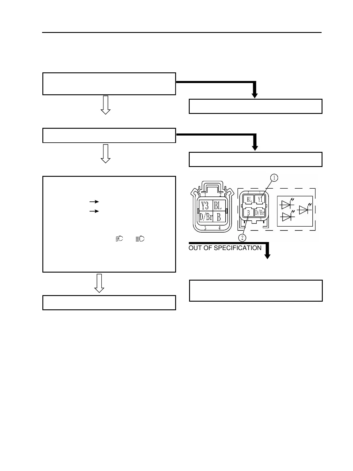
• Connect the pocket tester (DC 20 V) to the
bulb socket connector.
Tester (+) lead Dark/Brown terminal ①
Tester (–) lead Black terminal ②
• Turn the main switch to “ON”.
• Turn the light switch to “ ” or “ ”.
• Check the voltage (12 V) of the “Yellow”
lead on the bulb socket connector.
This circuit is not faulty.
Replace the bulb and/or bulb socket.
Replace the brake light switch.
The wiring circuit from the main switch to the
bulb socket connector is faulty, repair it.