45
• The trunk secondary port (Twenty-FiveGigE 1/0/2) is a tagged member of primary VLAN 10 and
secondary VLAN 11.
• The host port (Twenty-FiveGigE 1/0/3) is an untagged member of primary VLAN 10 and
secondary VLAN 12.
Example: Configuring Layer 3 communication for secondary
VLANs
Network configuration
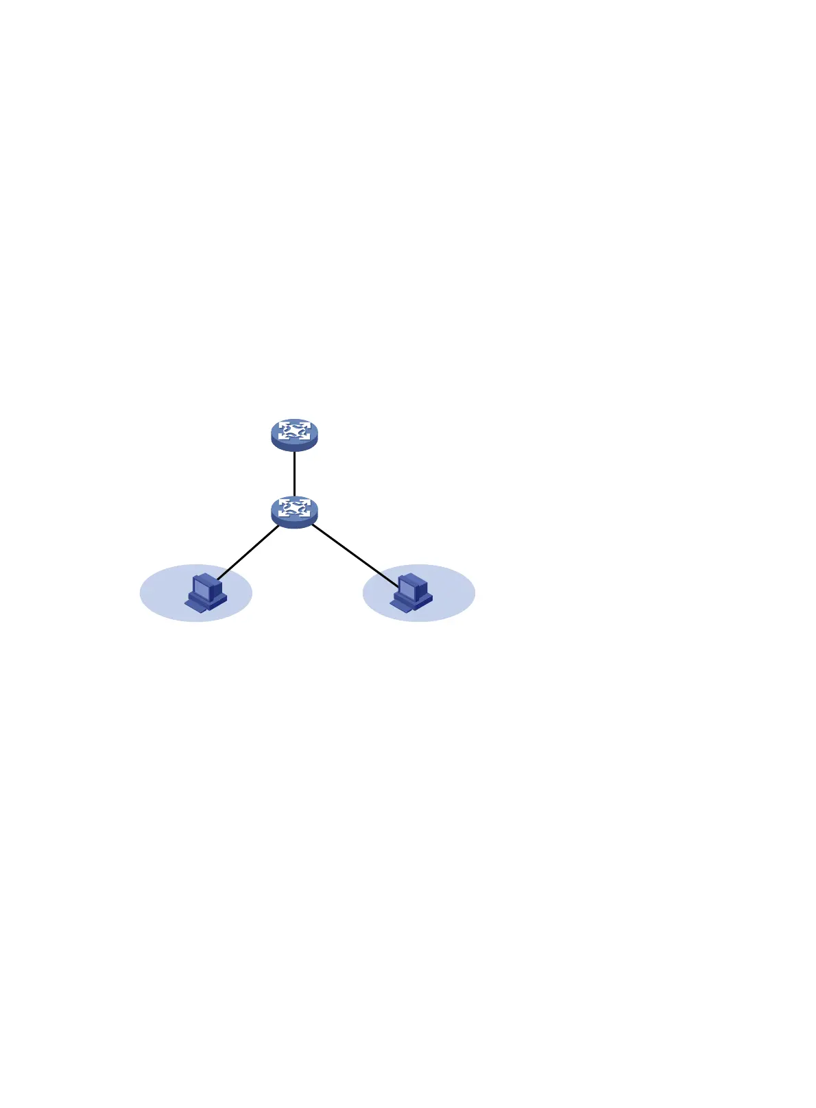
As shown in Figure 12, configure the private VLAN feature to meet the following requirements:
• Primary VLAN 10 on Device A is associated with secondary VLANs 2 and 3. The IP address of
VLAN-interface 10 is 192.168.1.1/24.
• Twenty-FiveGigE 1/0/1 belongs to VLAN 10. Twenty-FiveGigE 1/0/2 and Twenty-FiveGigE
1/0/3 belong to VLAN 2 and VLAN 3, respectively.
• Secondary VLANs are isolated at Layer 2 but interoperable at Layer 3.
Figure 12 Network diagram
Procedure
# Create VLAN 10 and configure it as a primary VLAN.
<DeviceA> system-view
[DeviceA] vlan 10
[DeviceA-vlan10] private-vlan primary
[DeviceA-vlan10] quit
# Create VLANs 2 and 3.
<DeviceA> system-view
[DeviceA] vlan 2 to 3
# Associate primary VLAN 10 with secondary VLANs 2 and 3.
[DeviceA] vlan 10
[DeviceA-vlan10] private-vlan primary
[DeviceA-vlan10] private-vlan secondary 2 3
[DeviceA-vlan10] quit
# Configure the uplink port (Twenty-FiveGigE 1/0/1) as a promiscuous port of VLAN 10.
[DeviceA] interface twenty-fivegige 1/0/1
[DeviceA-Twenty-FiveGigE1/0/1] port private-vlan 10 promiscuous
[DeviceA-Twenty-FiveGigE1/0/1] quit
VLAN 2 VLAN 3
VLAN 10
Device A
Device B
Vlan-int10
192.168.1.1/24
WGE1/0/3WGE1/0/2
WGE1/0/1

 Loading...


