3
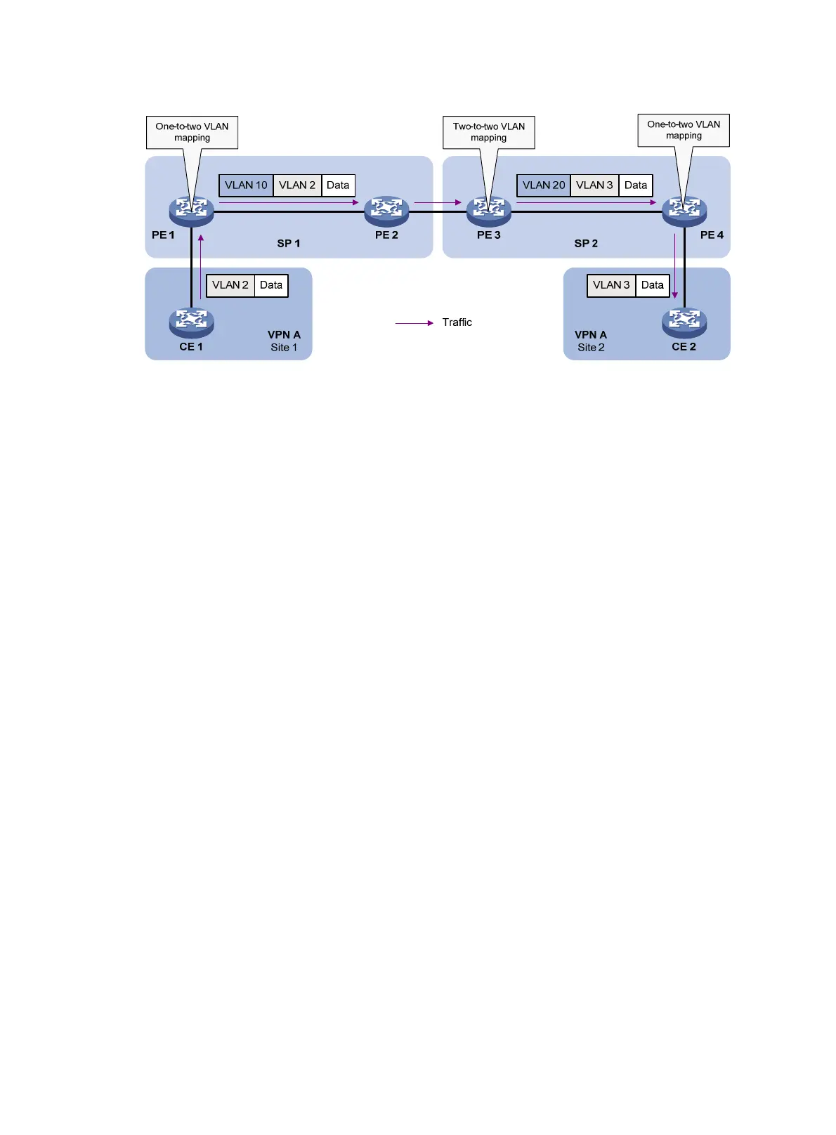
Figure 2 Application scenario of one-to-two and two-to-two VLAN mapping
As shown in Figure 2, Site 1 and Site 2 of VPN A are in VLAN 2 and VLAN 3, respectively. The SP 1
network assigns SVLAN 10 to Site 1. The SP 2 network assigns SVLAN 20 to Site 2. When the
packet from Site 1 arrives at PE 1, PE 1 tags the packet with SVLAN 10 by using one-to-two VLAN
mapping.
When the double-tagged packet from the SP 1 network arrives at the SP 2 network interface, PE 3
processes the packet as follows:
• Replaces SVLAN tag 10 with SVLAN tag 20.
• Replaces CVLAN tag 2 with CVLAN tag 3.
One-to-two VLAN mapping provides the following benefits:
• Enables a customer network to plan its CVLAN assignment without conflicting with SVLANs.
• Adds a VLAN tag to a tagged packet and expands the number of available VLANs to 4094 ×
4094.
• Reduces the stress on the SVLAN resources, which were 4094 VLANs in the SP network
before the mapping process was initiated.
VLAN mapping implementations
Figure 3 shows a simplified network that illustrates basic VLAN mapping terms.
Basic VLAN mapping terms include the following:
• Uplink traffic—Traffic transmitted from the customer network to the service provider network.
• Downlink traffic—Traffic transmitted from the service provider network to the customer
network.
• Network-side port—A port connected to or closer to the service provider network.
• Customer-side port—A port connected to or closer to the customer network.

 Loading...


