61
Figure 23 MSTIs mapped to different VLANs
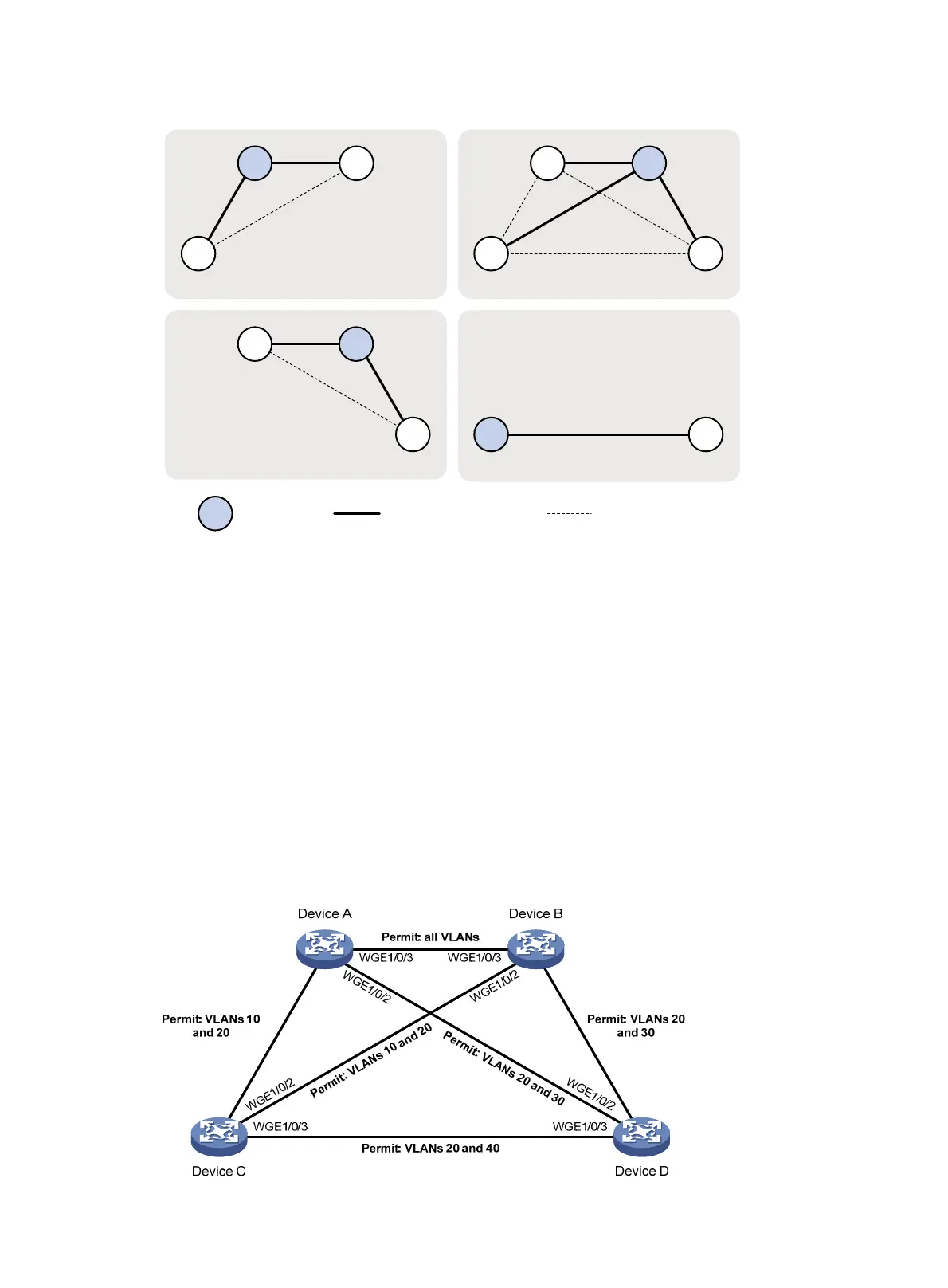
Example: Configuring PVST
Network configuration
As shown in Figure 24, Device A and Device B work at the distribution layer, and Device C and
Device D work at the access layer.
Configure PVST to meet the following requirements:
• Frames of a VLAN are forwarded along the spanning trees of the VLAN.
• VLAN 10, VLAN 20, and VLAN 30 are terminated on the distribution layer devices, and VLAN
40 is terminated on the access layer devices.
• The root bridge of VLAN 10 and VLAN 20 is Device A.
• The root bridge of VLAN 30 is Device B.
• The root bridge of VLAN 40 is Device C.
Figure 24 Network diagram
A
B
A B
C D
C
B
C
MSTI 1 mapped to VLAN 10
A
D D
Root bridge Normal link Blocked link
MSTI 3 mapped to VLAN 30
MSTI 0 mapped to VLAN 20
MSTI 4 mapped to VLAN 40
W
G
E
1
/
0
/
1
W
G
E
1
/
0
/
1
W
G
E
1/
0
/
1
W
G
E
1
/
0/
1

 Loading...


