64
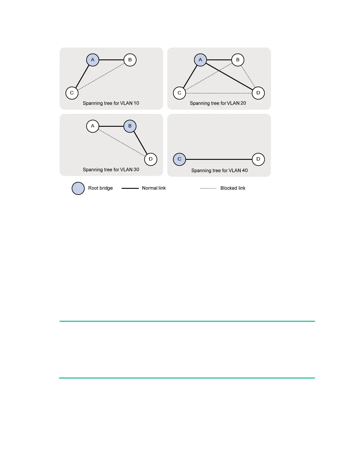
Figure 25 VLAN spanning tree topologies
Example: Configuring DRNI with PVST
Network configuration
As shown in Figure 26, Device A and Device B work at the distribution layer, and Device C and
Device D work at the access layer.
Configure DRNI on Device A and Device B. In the DR system, Device A is the primary DR device,
and Device B is the secondary DR device.
Configure PVST on the devices to meet the following requirements:
• Frames of a VLAN are forwarded along the spanning trees of the VLAN.
• VLAN 10, VLAN 20, and VLAN 30 are terminated on the distribution layer devices.
• The root bridge of VLAN 10, VLAN 20, and VLAN 30 is the DR system formed by Device A and
Device B.
NOTE:
•
As a best practice, do not connect ports on Device A and Device B that have the same port ID with each
other, for example Layer 2 aggregate ports. Otherwise, when Device A and Device B communicate through
the link, the spanning tree protocol determines that the device receives its own BPDUs. Loop guard will
block the link, though spanning tree features are not affected.
• You can view port IDs of interfaces on the device by using the display stp interface command.
• The preceding restrictions do not apply to IPPs and their member ports.

 Loading...


