12
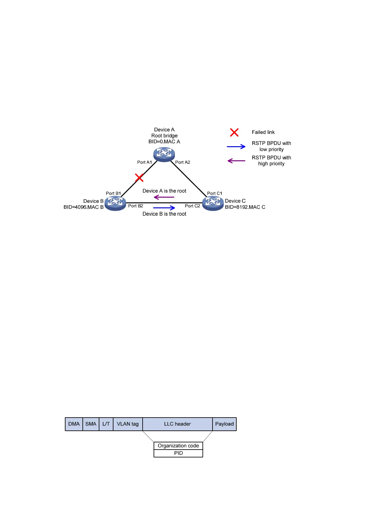
As shown in Figure 6, Device A is the root bridge. The priority of Device B is higher than the priority of
Device C. Port C2 on Device C is blocked.
When the link between Device A and Device B fails, the following events occur:
1. Device B sends an RSTP BPDU with itself as the root bridge to Device C.
2. Device C compares the RSTP BPDU with its own BPDU.
3. Because the RSTP BPDU from Device B has a lower priority, Device C sends its own BPDU to
Device B.
4. Device B considers that Port B2 is the root port and stops sending RSTP BPDUs to Device C.
Figure 6 BPDU processing in RSTP
About PVST
In an STP- or RSTP-enabled LAN, all bridges share one spanning tree. Traffic from all VLANs is
forwarded along the spanning tree, and ports cannot be blocked on a per-VLAN basis to prune loops.
PVST allows every VLAN to have its own spanning tree, which increases usage of links and
bandwidth. Because each VLAN runs RSTP independently, a spanning tree only serves its VLAN.
A PVST-enabled H3C device can communicate with a third-party device that is running Rapid PVST
or PVST. The PVST-enabled H3C device supports fast network convergence like RSTP when
connected to PVST-enabled H3C devices or third-party devices enabled with Rapid PVST.
PVST protocol frames
As shown in Figure 7, a PVST BPDU uses the same format as an RSTP BPDU except the following
differences:
• The destination MAC address of a PVST BPDU is 01-00-0c-cc-cc-cd, which is a private MAC
address.
• Each PVST BPDU carries a VLAN tag. The VLAN tag identifies the VLAN to which the PVST
BPDU belongs.
• The organization code and PID fields are added to the LLC header of the PVST BPDU.
Figure 7 PVST BPDU format

 Loading...


