1
Configuring Ethernet link aggregation
About Ethernet link aggregation
Ethernet link aggregation bundles multiple physical Ethernet links into one logical link (called an
aggregate link). Link aggregation provides the following benefits:
• Increased bandwidth beyond the limits of a single individual link. In an aggregate link, traffic is
distributed across the member ports.
• Improved link reliability. The member ports dynamically back up one another. When a member
port fails, its traffic is automatically switched to other member ports.
Ethernet link aggregation application scenario
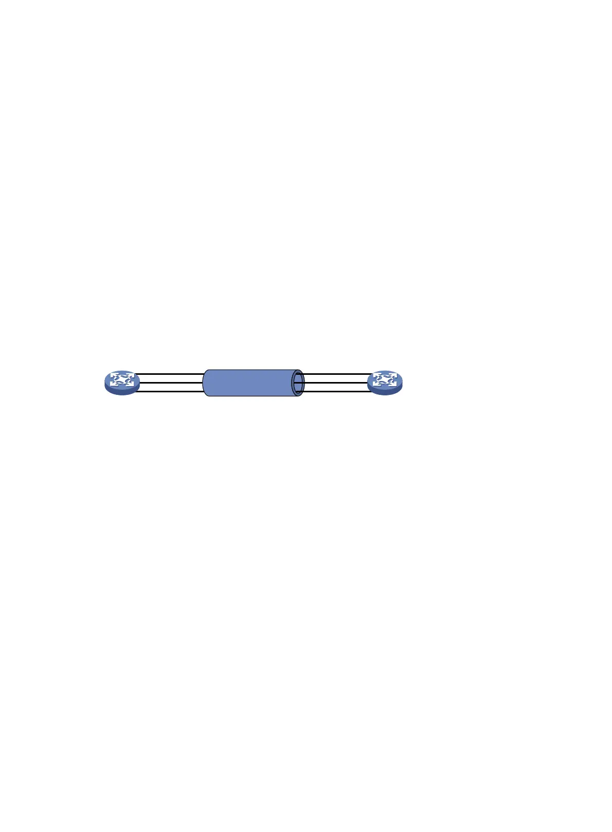
As shown in Figure 1, Device A and Device B are connected by three physical Ethernet links. These
physical Ethernet links are combined into an aggregate link called link aggregation 1. The bandwidth
of this aggregate link can reach up to the total bandwidth of the three physical Ethernet links. At the
same time, the three Ethernet links back up one another. When a physical Ethernet link fails, the
traffic transmitted on the failed link is switched to the other two links.
Figure 1 Ethernet link aggregation diagram
Aggregate interface, aggregation group, and member port
Each link aggregation is represented by a logical aggregate interface. Each aggregate interface has
an automatically created aggregation group, which contains member ports to be used for
aggregation. The type and number of an aggregation group are the same as its aggregate interface.
Supported aggregate interface types
An aggregate interface can be one of the following types:
• Layer 2—A Layer 2 aggregate interface is created manually. The member ports in a Layer 2
aggregation group can only be Layer 2 Ethernet interfaces.
• Layer 3—A Layer 3 aggregate interface is created manually. The member ports in its Layer 3
aggregation group can only be Layer 3 Ethernet interfaces.
On a Layer 3 aggregate interface, you can create subinterfaces. A Layer 3 aggregate
subinterface processes traffic only for the VLAN numbered with the same ID as the subinterface
number.
The port rate of an aggregate interface equals the total rate of its Selected member ports. Its duplex
mode is the same as that of the Selected member ports. For more information about Selected
member ports, see "Aggregation states of member p
orts in an aggregation group."
Aggregation states of member ports in an aggregation group
A member port in an aggregation group can be in any of the following aggregation states:
• Selected—A Selected port can forward traffic.
• Unselected—An Unselected port cannot forward traffic.
Port A2
Port A1
Port A3
Link aggregation 1
Port B2
Port B1
Port B3
Device A Device B

 Loading...


