12
• The ceiling is lower than or equal to the maximum suppress limit supported.
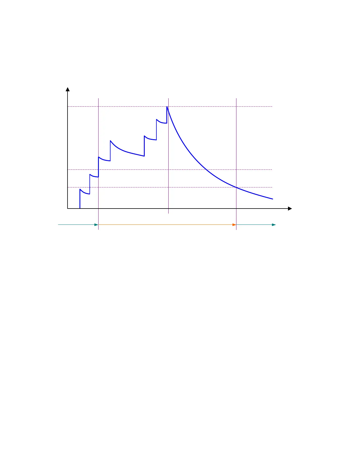
Figure 1 sho
ws the change rule of the penalty value. The lines t
0
and t
2
indicate the start time and
end time of the suppression, respectively. The period from t
0
to t
2
indicates the suppression period, t
0
to t
1
indicates the max-suppress-time, and t
1
to t
2
indicates the complete decay period.
Figure 1 Change rule of the penalty value
Restrictions and guidelines
• The dampening, link-delay, and port link-flap protect enable commands are
mutually exclusive on an interface.
• The
dampening command does not take effect on the administratively down events. When
you execute the
shutdown command, the penalty restores to 0, and the interface reports the
down event to the upper-layer protocols.
• Do not enable the dampening feature on an interface with RRPP, MSTP, or Smart Link enabled.
Procedure
1. Enter system view.
system-view
2. Enter Ethernet interface view.
interface interface-type interface-number
3. Enable dampening on the interface.
dampening [ half-life reuse suppress max-suppress-time ]
By default, interface dampening is disabled on Ethernet interfaces.
Enabling link flapping protection on an interface
About link flapping protection
Link flapping on an interface changes network topology and increases the system overhead. For
example, in an active/standby link scenario, when interface status on the active link changes
Not suppressed Not suppressedSuppressed
Penalty
Time
Reuse limit
Suppress limit
Ceiling
t
0 t1
t2

 Loading...


