7
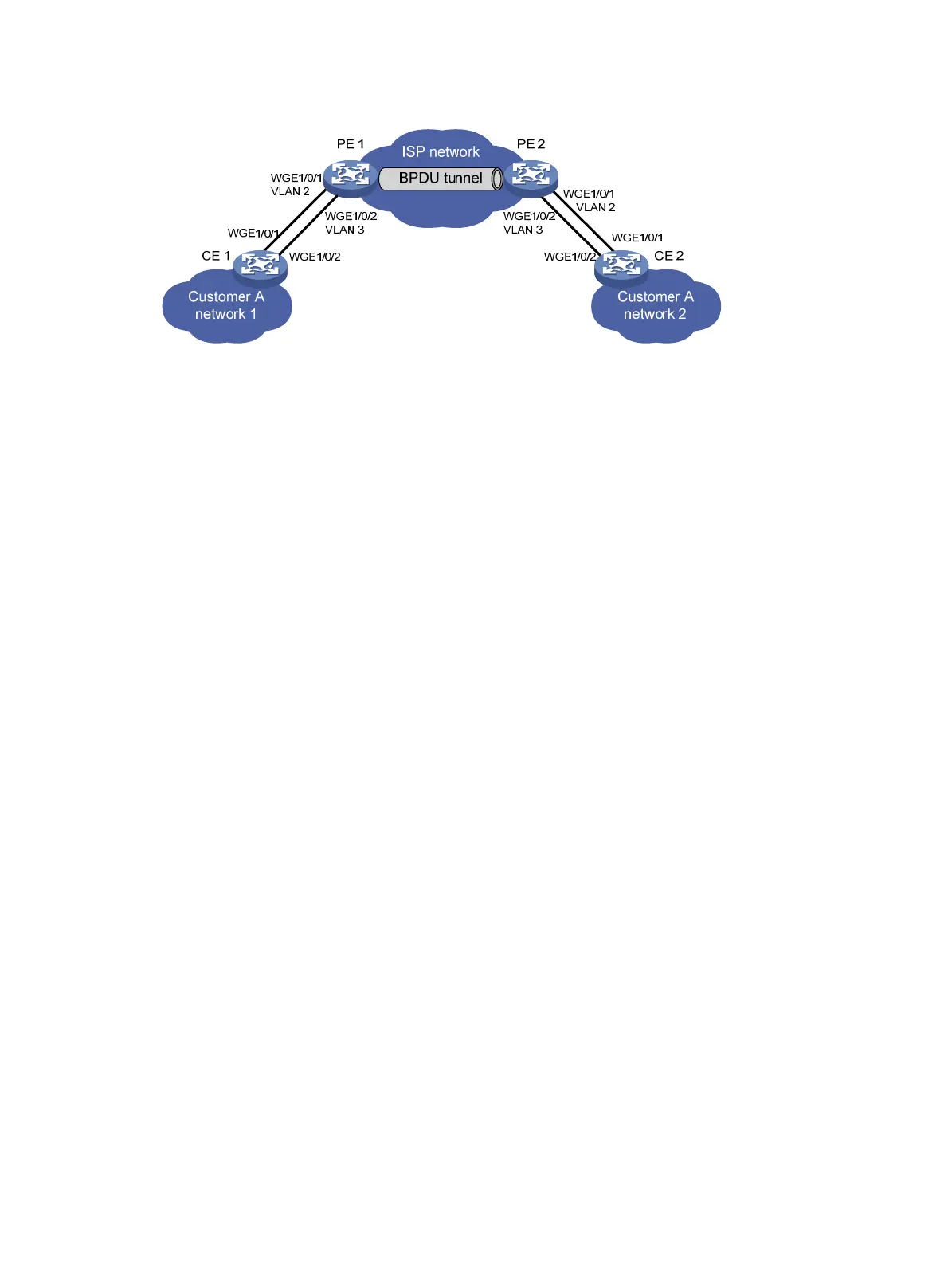
Figure 5 Network diagram
Requirements analysis
To meet the network requirements, perform the following tasks:
• For Ethernet link aggregation to operate correctly, configure VLANs on the PEs to ensure
point-to-point transmission between CE 1 and CE 2 in an aggregation group.
{ Set the PVIDs to VLAN 2 and VLAN 3 for Twenty-FiveGigE 1/0/1 and Twenty-FiveGigE
1/0/2 on PE 1, respectively.
{ Configure PE 2 in the same way PE 1 is configured.
{ Configure ports that connect to the CEs as trunk ports.
• To retain the VLAN tag of the customer network, enable QinQ on Twenty-FiveGigE 1/0/1 and
Twenty-FiveGigE 1/0/2 on both PE 1 and PE 2.
• For packets from any VLAN to be transmitted, configure all ports in the service provider
network as trunk ports.
Procedure
1. Configure CE 1:
# Configure Layer 2 aggregation group Bridge-Aggregation 1 to operate in dynamic
aggregation mode.
<CE1> system-view
[CE1] interface bridge-aggregation 1
[CE1-Bridge-Aggregation1] port link-type access
[CE1-Bridge-Aggregation1] link-aggregation mode dynamic
[CE1-Bridge-Aggregation1] quit
# Assign Twenty-FiveGigE 1/0/1 and Twenty-FiveGigE 1/0/2 to Bridge-Aggregation 1.
[CE1] interface twenty-fivegige 1/0/1
[CE1-Twenty-FiveGigE1/0/1] port link-aggregation group 1
[CE1-Twenty-FiveGigE1/0/1] quit
[CE1] interface twenty-fivegige 1/0/2
[CE1-Twenty-FiveGigE1/0/2] port link-aggregation group 1
[CE1-Twenty-FiveGigE1/0/2] quit
2. Configure CE 2 in the same way CE 1 is configured. (Details not shown.)
3. Configure PE 1:
# Create VLANs 2 and 3.
<PE1> system-view
[PE1] vlan 2
[PE1-vlan2] quit

 Loading...


