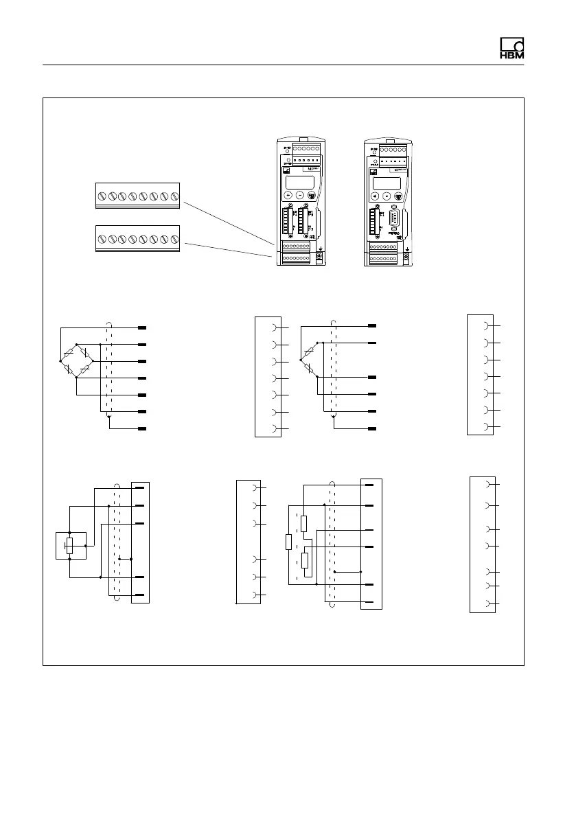
Electrical connection
28 A0293_06_E00_03 HBM: public MP85A
ye
Strain gage and inductive full bridges,
piezoresistive transducers
1
4
6
Hsg.
5
wh
bk
rd
bl
gn
gr
ye
Cable color code: wh = white; bk = black; bl = blue; rd = red; ye = yellow; gn = green; gr = gray
4
1
2
3
Potentiometric transducers
*)
Cable shield
wh
bk
bl
gn
gr
Sense lead (+)
Cable shield
Strain gage and inductive half bridges
LVDT transducers
M
e
a
s
u
r
e
m
e
n
t
s
i
g
n
a
l
(
+
)
Measurement
signal (+)
Measurement signal (-)
Sense lead (+)
Hsg.
Sense lead (-)
Cable shield
Measurement
signal (+)
Transducer
supply (-)
Transducer
supply (+)
Sense lead (+)
Cable shield
MP85A(-S)
Screw terminals 5 and 6
for transducer connection
MP85ADP(-S)
MP85ADP-PN(-S)
SENSOR X
1 8
SENSOR Y
1 8
*)
) Half bridge function
Sense lead (+)
4
Hsg.
Transducer supply (-)
Transducer
supply (-)
Transducer supply (+)
Transducer supply (+)
Sense lead (-) Sense lead (-)
Measurement
signal (+)
Transducer
supply (-)
Transducer
supply (+)
Measurement
signal (-)
Sense lead (-)
1
2
4
5
3
Hsg.
6
2
1
2
1
2
3
5
3
5
3
Measurement signal (+)
Fig. 5.4 Connecting different transducers in carrier-frequency amplifier mode