Electrical connection
30 A0293_06_E00_03 HBM: public MP85A
If the cables of transducers in a 6-wire circuit are >50 m in length, you must
loop resistors with half the value of the transducer’s bridge resistance (R
B
/2) in
the sense leads.
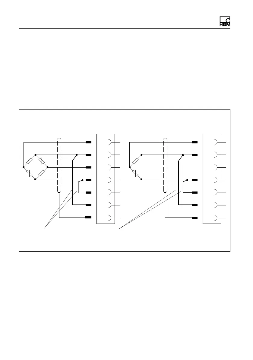
When connecting a transducer in a 4-wire configuration, connect the sense
leads to the appropriate transducer supply cables (pin 3 to pin 2 and pin 5 to
pin 4). For transducer cables >50 m in length, use a resistor with half the value
of the transducer’s bridge resistance (R
B
/2) for each cable, instead of the
above connection.
Cable color code: wh = white; bk = black; bl = blue; rd = red; ye = yellow; gn = green; gr = gray
1
2
4
6
Hsg.
5
3
wh
bk
rd
bl
ye
Feedback bridges for 4-wire configuration
4-wire connection:
Full bridge
1
2
4
6
Hsg.
5
3
wh
bk
bl
ye
4-wire connection:
Half bridge
Fig. 5.6 Transducer connection in 4-wire configuration (no TEDS possible)
Open circuit detection
MP85A process controllers have open circuit detection for the connected
transducers.
The bridge excitation voltage cables and measurement signal cables are
monitored. In measurement signal and bridge excitation voltage cables, a
broken wire in a single lead is also reported as a fault.