35
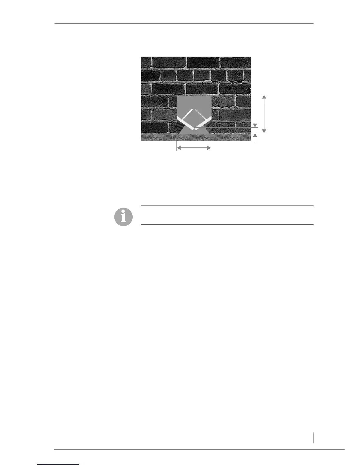
1 Sloping floor panels
A) 28 cm
B) min. 5.5 cm
C) 25 cm
C
EILINGS, WALLS AND ACCESS
POINTS
The walls and ceiling must be dry. Make sure that things are airtight
owing to the dust generated and the danger of condensation on cold
winter days.
The surrounding walls must be able to bear the weight and pressure
produced by the pellets (density 650 kg/m
2
).
In practice, the following wall thicknesses have proved adequate.
• Medium weight vertically perforated brick:
– 11.5 cm plastered on both sides
• Solid concrete:
– 10 cm (steel reinforced)
• Aerated concrete:
– 11.5 cm plastered on both sides
• Wooden framed wall:
– approx. 12 cm thick beams
– with planking on both sides made of 15 - 20 mm timber
– Beam spacing approx. 62.5 cm
The conditions for proper design include a wall length of max. 5 m
and a height of max. 2.5 m, with a well-designed connection
between the walls and ceiling on all sides.
Figure 4/8 - Passage through the wall