17 – 262 HEIDENHAIN Service Manual iTNC 530
17.2 Power Supply for "Control-Is-Ready Signal"
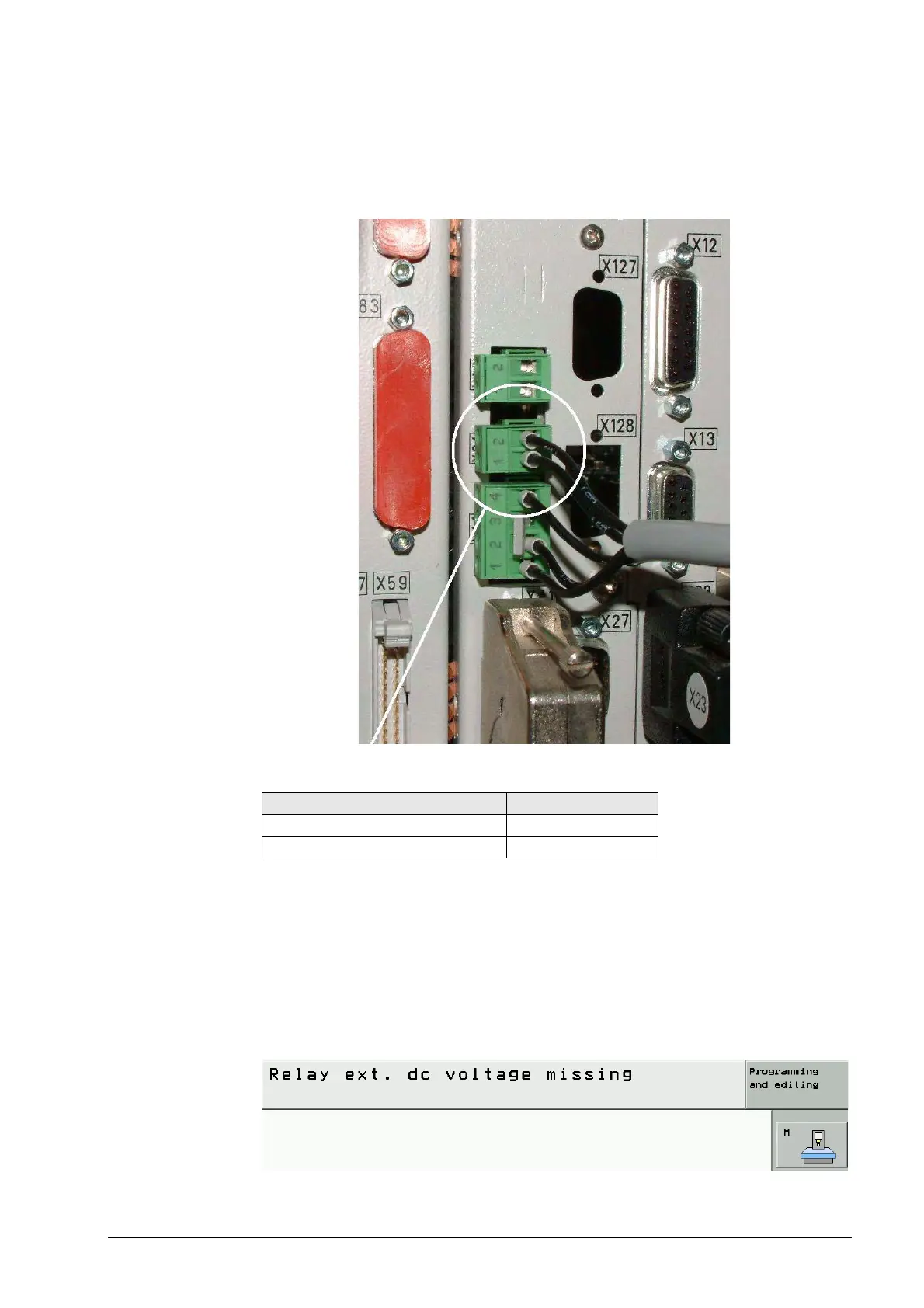
X34:
Power supply for
"Control-Is-Ready"
signal output
The control-is-ready signal output is powered with 24 Vdc provided by the compact inverter or
the power supply unit. The voltage is connected to terminal X34 of the MC.
Pin layout:
If a HEIDENHAIN inverter system is located in the electrical cabinet, connector X72 generally
supplies the 24 V from the inverter. See ”Annex: Principle of Function of the iTNC 530 Control”
on page 2 – 657).
If there is a non-HEIDENHAIN inverter system in the electrical cabinet, the power supply unit in
the electrical cabinet supplies the 24 V.
Error messages If the 24 V supply on X34 for the Control-Is-Ready output is missing, the machine cannot be
switched on completely. The EMERGENCY STOP chain is interrupted.
The control remains at the message Relay ext. dc voltage missing:
Connecting terminal X34 on the MC Pin layout
1 +24 V
20 V

 Loading...


