July 2010 20 – 323
20 Interface to the Drives
20.1 Digital PWM Interface
20.1.1 Introduction
The position, speed and current controllers are located in the HEIDENHAIN control.
The "result" of the position, speed and current control is pulse-width modulated.
Via PWM interfaces (PWM = pulse-width-modulation) digital servo amplifiers are controlled.
Digital drive systems are also referred to as inverter systems.
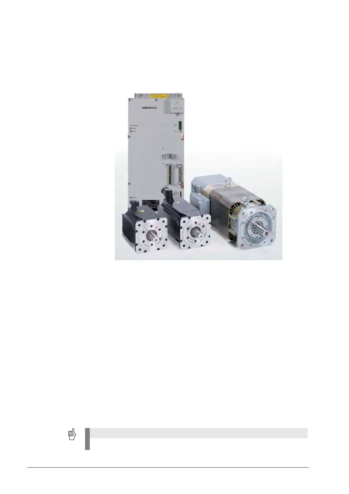
For digital drives three-phase ac motors are used.
The most important motors are:
Synchronous motors (e.g., HEIDENHAIN QSY axis motors)
Asynchronous motors (e.g., HEIDENHAIN QAN spindle motors)
Linear motors
Torque motors
PWM outputs Following PWM interfaces are located on the CC 422 or CC 424 (B)
(every digital axis/spindle has its own PWM ribbon-cable connector):
X51 to X56
X57 to X64 (depending on the expansion stage)
Assignment of the
PWM outputs
MP 100 is read from the right to the left and contains the information which axis is the first, the
second, the third axis, etc.
MP 100 must not be changed!

 Loading...


