July 2010 19 – 319
19.4 Troubleshooting
Examining the
encoders
8 See “Encoder Interface” on page 18 – 277.
Examining the
reference mark
8 See “Further Examination of Position and Speed Encoders” on page 18 – 308.
Examining the
switch signal of the
trip dog
8 Move the axis to the presumed position of the trip dog.
8 Ask the machine manufacturer for the PLC input for the switch signal.
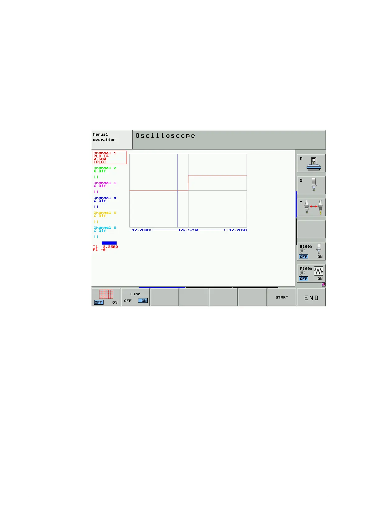
8 Observe the switch signal, e.g. in the integrated oscillocope or in the PLC logic diagram.
Figure: Switch signal of the trip dog in the integrated oscilloscope

 Loading...


