July 2010 27 – 491
Connector on the
front panel
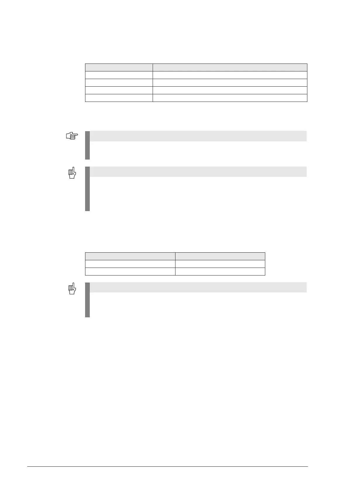
Supply voltage: 400 V ± 10%
Pin layout:
Equipment ground (YL/GY) ≥ 10 mm
2
50-pin ribbon cable For connection to connector X69/X169 of the CC, See “X69: NC power supply and control
signals” on page 27 – 481.
5V terminal on the
front panel
Pin layout:
Connecting terminal Pin layout
UU
a
a. Connecting cable 1.5 mm
2
VV
a
+U
DC
DC-link voltage of the non-HEIDENHAIN inverster system
-U
DC
DC-link voltage of the non-HEIDENHAIN inverster system
You must connect the supply voltage to the terminals U and V via an isolating transformer
(300 VA, basic insulation as per EN 50 178 and VDE 0550).
Do not ground this isolating transformer on the secondary side!
The isolating transformer decouples the dc-link voltage from ground. Grounding the isolating
transformer on the secondary side leads to an addition of the dc-link voltage and the supply
voltage. This would overload and thus destroy the UV 105 B.
Wire color of 5-V connection 5 V terminal on CC 42x (B)
Black 0 V
Red +5 V
For mounting the UV 105 B, the additional 5V lines must be connected with the correct
polarity!
Otherwise there will be a short circuit of these lines on the 5V ribbon wires.

 Loading...


