HEIDENHAIN MANUALplus 620 215
4.7 Front and Rear Face Contours
Circular pattern on front/rear face G402-Geo
G402 defines a circular hole pattern or figure pattern on the front or
rear face. G402 is effective for the hole/figure defined in the following
block (G300 to 305, G307).
Parameters
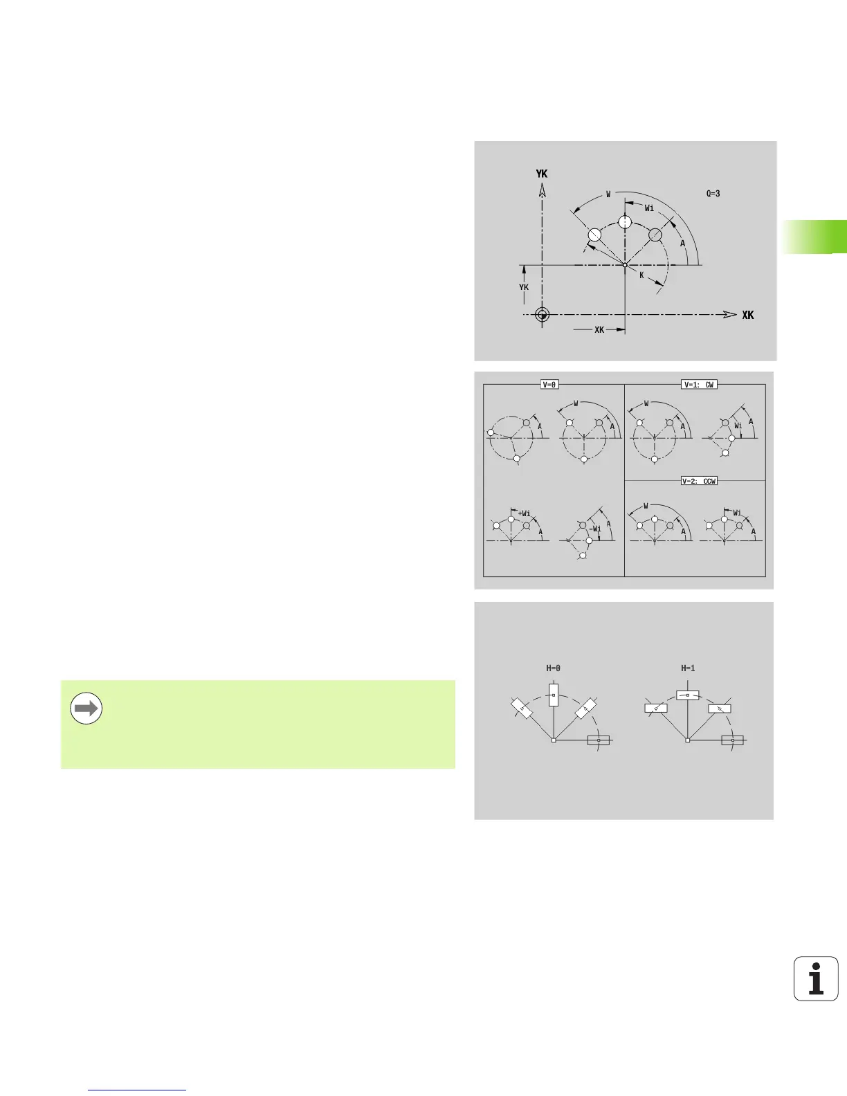
Q Number of figures
K Pattern diameter
A Starting angle—position of the first figure; reference: XK axis;
(default: 0°)
W Final angle—position of the last figure; reference: XK axis;
(default: 360°)
Wi Angle between figures
V Direction—orientation (default: 0)
V=0, without W: Figures are arranged on a full circle
V=0, with W: Figures are arranged on the longer circular arc
V=0, with Wi: The algebraic sign of Wi defines the direction
(Wi<0: clockwise)
V=1, with W: Clockwise
V=1, with Wi: Clockwise (algebraic sign of Wi has no effect)
V=2, with W: Counterclockwise
V=2, with Wi: Counterclockwise (algebraic sign of Wi has no
effect)
XK Center in Cartesian coordinates
YK Center in Cartesian coordinates
H Position of the figures (default: 0)
H=0: Normal position; the figures are rotated about the circle
center (rotation)
H=1: Original position; the position of the figures relative to
the coordinate system remains unchanged (translation)
Program the hole/figure in the following block without a
center. Exception: circular slot: see “Circular pattern
with circular slots” on page 204.
The milling cycle (MACHINING section) calls the hole/
figure in the following block—not the pattern definition.

 Loading...


