324 ISO Programming
4.26 Milling Cycles
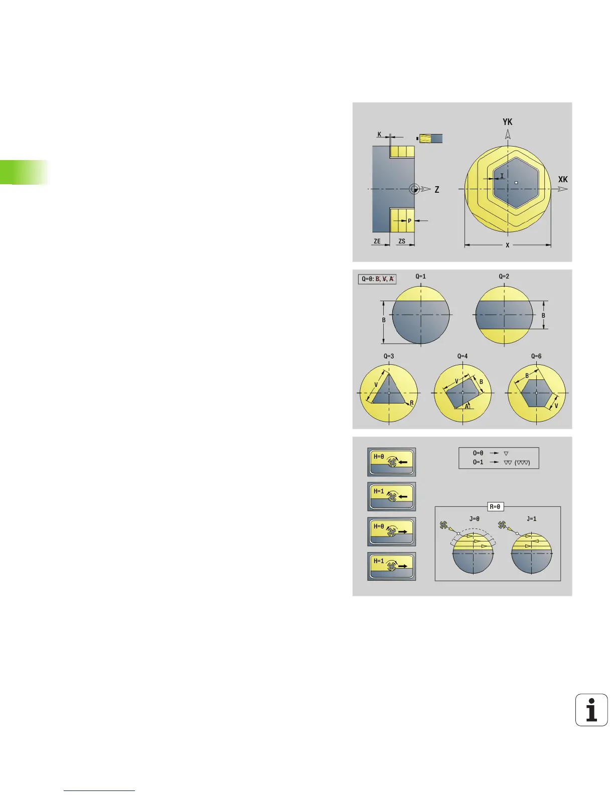
Area milling, face G797
Depending on Q, G797 mills surfaces, a polygon, or the figure defined
in the command following G797.
Parameters
X Limit diameter
ZS Milling top edge
ZE Milling floor
B Width across flats (omit for Q=0): B defines the remaining
material. For an even number of surfaces, you can program B
as an alternative to V.
Q=1: B=Residual depth
Q>=2: B=Width across flats
V Edge length (omitted for Q=0)
R Chamfer/rounding
A Inclination angle (reference: see help graphic) —omitted for
Q=0
Q Number of surfaces (default: 0): Range 0 <= Q <= 127
Q=0: G797 is followed by a figure definition (G301 to G307,
G80) or a closed contour definition (G100 to G103, G80)
Q=1: One surface
Q=2: Two surfaces offset by 180°
Q=3: Triangle
Q=4: Rectangle, square
Q>4: Polygon
P Maximum approach (default: total depth in one infeed)
U Overlap factor (default: 0.5): Minimum overlap of milling paths
= U*milling diameter
I Contour-parallel oversize
K Oversize in Z
F Approach feed (infeed rate)
E Reduced feed rate for circular elements (default: current feed
rate)
H Cutting direction (default: 0): The cutting direction can be
changed with H and the direction of tool rotation (see help
graphic)
0: Up-cut milling
1: Climb milling

 Loading...


