310 ISO Programming
4.24 Front/Rear-Face Machining
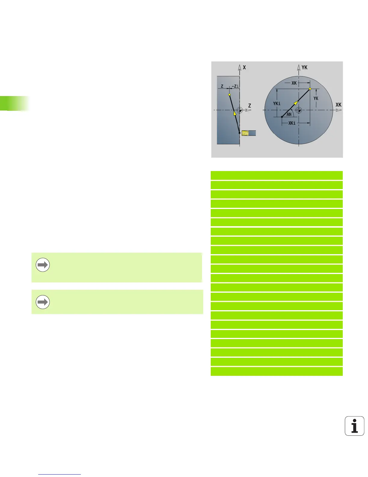
Linear path on front/rear face G101
G101 moves the tool on a linear path at the feed rate to the “end
point.”
Example: G101
. . .
N1 T70 G197 S1200 G195 F0.2 M104
N2 M14
N3 G110 C0
N4 G0 X110 Z2
N5 G100 XK50 YK0
N6 G1 Z-5
N7 G42 Q1
N8 G101 XK40 [linear path on face]
N9 G101 YK30
N10 G103 XK30 YK40 R10
N11 G101 XK-30
N12 G103 XK-40 YK30 R10
N13 G101 YK-30
N14 G103 XK-30 YK-40 R10
N15 G101 XK30
N16 G103 XK40 YK-30 R10
N17 G101 YK0
N18 G100 XK110 G40
N19 G0 X120 Z50
N20 M15
. . .
Parameters
X Final point (diameter)
C Final angle—for angle direction, see help graphic
XK Final point (Cartesian)
YK Final point (Cartesian)
Z Final point (default: current Z position)
Parameters for contour description (G80)
AN Angle to positive XK axis
BR Chamfer/rounding. Defines the transition to the next contour
element. When entering a chamfer/rounding, program the
theoretical end point.
No entry: Tangential transition
BR=0: No tangential transition
BR>0: Rounding radius
BR<0: Width of chamfer
Q Point of intersection. End point if the line segment intersects
a circular arc (default: 0):
Q=0: Near point of intersection
Q=1: Far point of intersection
Programming:
X, C, XK, YK, Z: Absolute, incremental or modal
Program either X–C or XK–YK
Using the parameters AN, BR and Q is only allowed if the
contour description is concluded by G80 and used for a
cycle.

 Loading...


