HEIDENHAIN MANUALplus 620 265
4.18 Contour Definitions in the Machining Section
4.18 Contour Definitions in the
Machining Section
Cycle end / Simple contour G80
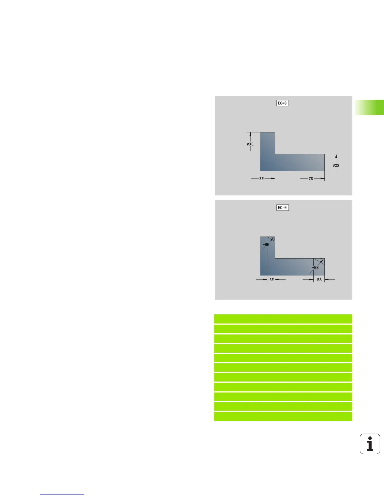
By programming G80 (with parameters), a turning contour consisting
of more than one element can be defined in one NC block. G80
(without parameters) ends a contour definition directly after a cycle.
“IC” and “KC” are used in the control to show the chamfer/rounding
cycles.
Example: G80
N1 T3 G95 F0.25 G96 S200 M3
N2 G0 X120 Z2
N3 G810 P3
N4 G80 XS60 ZS-2 XE90 ZE-50 BS3 BE-2 RC5
N5 ...
N6 G0 X85 Z2
N7 G810 P5
N8 G0 X0 Z0
N9 G1 X20
N10 G1 Z-40
N11 G80
Parameters
XS Starting point of contour in X (diameter value)
ZS Starting point of contour in Z
XE Contour end point in X (diameter value)
ZE Contour end point in Z
AC Angle of 1st element (range 0°<=AC<90°)
WC Angle of 2nd element (range 0°<=AC<90°)
BS Chamfer/rounding arc at starting point
WS Angle for chamfer at starting point
BE Chamfer/rounding arc at end point
WE Angle for chamfer at end point
RC Radius
IC Chamfer width
KC Chamfer width
JC Execution (see cycle programming)
0: Simple contour
1: Expanded contour
EC Plunging contour
0: Rising contour
1: Plunging contour
HC Contour direction for finishing:
0: Longitudinal
1: Transverse

 Loading...


