342 ISO Programming
4.26 Milling Cycles
You can change the milling direction with the cutting direction H, the
machining direction Q and the direction of tool rotation (see following
table). Program only the parameters given in the following table.
For the machining direction Q=1 (from the outside toward
the inside), please note:
The contour must start with a linear element.
If the starting element is < WB, WB is reduced to the
length of the starting element.
The length of the starting element must not be less than
1.5 times the diameter of the milling cutter.
Cycle run
1 Starting position (X, Z, C) is the position before the cycle begins.
2 Calculates the number of cuts (infeeds to the milling planes,
infeeds in the milling depths) and the plunging positions and
paths for reciprocating or helical plunges.
3 Approaches to safety clearance and, depending on O, feeds to
the first milling depth or approaches helically or on a
reciprocating path.
4 Mills a plane.
5 Retracts by the safety clearance, returns and cuts to the next
milling depth.
6 Repeat steps 4 and 5 until the complete surface is milled.
7 Returns to retraction plane RB.
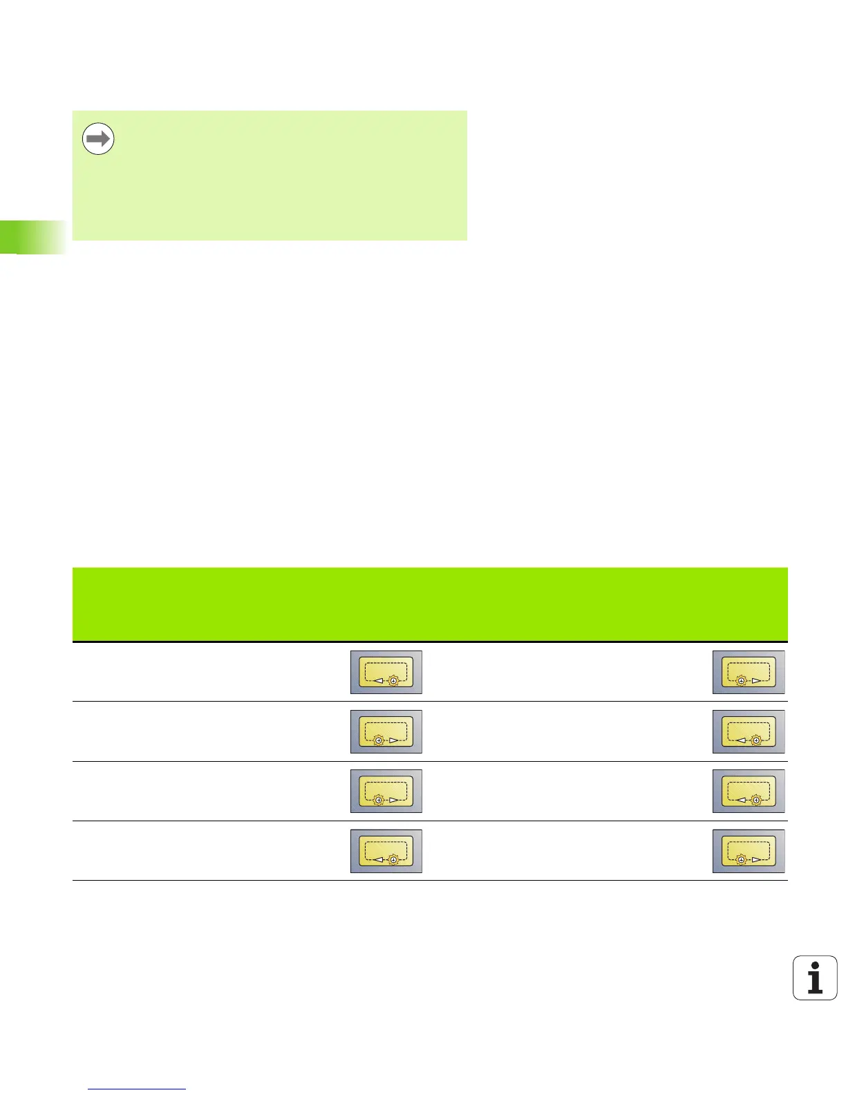
Pocket milling, roughing G845
Cutting
direction
Machining
direction
Direction
of tool
rotation
Execution
Cutting
direction
Machining
direction
Direction
of tool
rotation
Execution
Up-cut milling
(H=0)
From inside
(Q=0)
Mx03 Climb milling
(H=1)
From inside
(Q=0)
Mx03
Up-cut milling
(H=0)
From inside
(Q=0)
Mx04 Climb milling
(H=1)
From inside
(Q=0)
Mx04
Up-cut milling
(H=0)
From outside
(Q=1)
Mx03 Climb milling
(H=1)
From outside
(Q=1)
Mx03
Up-cut milling
(H=0)
From outside
(Q=1)
Mx04 Climb milling
(H=1)
From outside
(Q=1)
Mx04

 Loading...


