HEIDENHAIN MANUALplus 620 417
5.7 Milling Cycles for the Y Axis
G845 (Y axis)—Milling
You can change the cutting direction with the “cutting direction H,”
the “machining direction Q” and the direction of tool rotation (see
table G845 in the User's Manual). Program only the parameters given
in the following table.
See also:
G845—Fundamentals: Page 415
G845—Calculating hole positions: Page 416
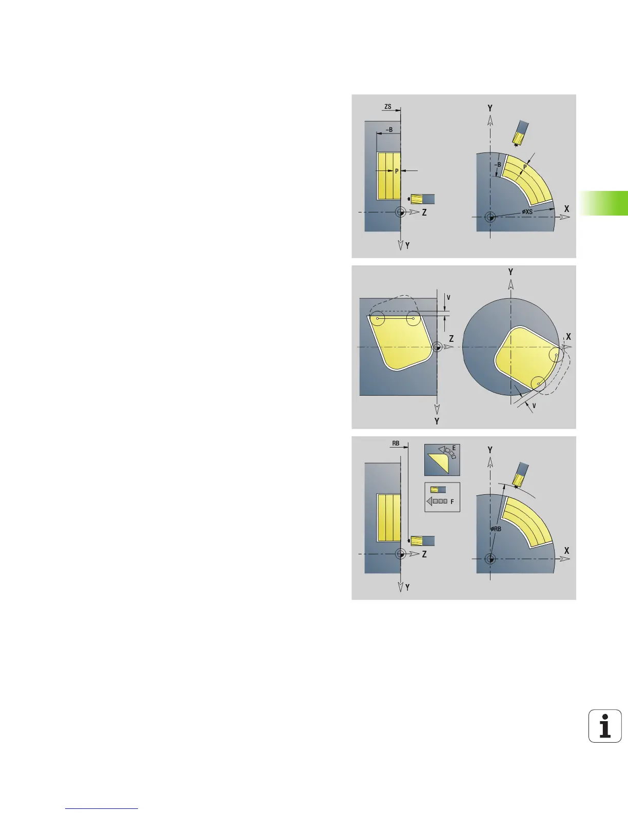
Parameters—Milling
ID Milling contour—name of the contour to be milled
NS Contour start block no.
Figures: Block number of the figure
Free closed contour: A contour element (not starting point)
B Milling depth (default: depth from the contour description)
P Maximum infeed (default: milling in one infeed)
XS Milling top edge in YZ plane (replaces the reference diameter
from the contour description)
ZS Milling top edge in XY plane (replaces the reference plane
from the contour description)
I Oversize in X direction (radius)
K Oversize in Z direction
U (Minimum) overlap factor. Defines the overlap of milling paths
(default: 0.5).
Overlap = U*milling diameter
V Overrun factor (default: 0.5). Defines the distance by which
the tool should pass the outside radius of the workpiece.
0: The defined contour is milled completely
0< V <= 1: Overrun = V*milling diameter
H Cutting direction (default: 0)
0: Up-cut milling
1: Climb milling
F Approach feed for infeed (default: active feed rate)
E Reduced feed rate for circular elements (default: current feed
rate)
RB Return plane (default: back to starting position)
XY plane: Retraction position in Z direction
YZ plane: Retraction position in X direction (diameter)
Q Machining direction (default: 0)
0: From the inside out (from the inside towards the outside)
1: From the outside in (from the outside towards the inside)
A Sequence for “Milling”: A=0 (default=0)

 Loading...


