48 smart.Turn Units
2.1 smart.Turn Units
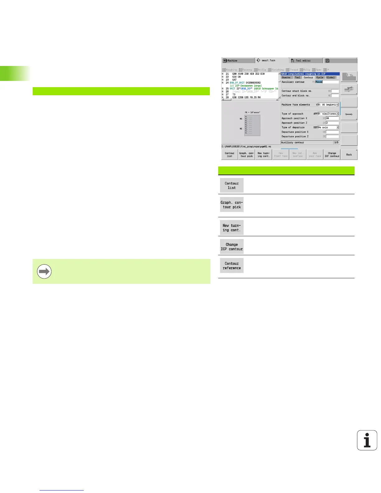
The Contour form
In the contour form you define the contours to be machined. A
difference is made between the direct contour definition (G80) and the
reference to an external contour definition (FINISHED part or
AUXIL_CONTOUR sections).
Soft keys in the ICP contour form
Opens the selection list of the contours
defined in the program.
Shows all contours in the graphics
window. Use the arrow keys for
selection.
Starts the ICP editor. First, enter the
desired contour name in FK.
Starts the ICP editor with the currently
selected contour.
Opens the graphics window for
selection of a part of a contour for NS
and NE.
ICP contour definition parameters
FK Auxiliary contour: Name of the contour to be machined.
You can select an existing contour or describe a new
contour with ICP.
NS Contour start block number: Beginning of contour section.
NE Contour end block number: End of contour section.
NE not programmed: The contour element NS is
machined in the direction of contour definition.
NS=NE programmed: The contour element NS is
machined opposite to the direction of contour definition.
V Machine form elements (default: 0).
A chamfer/rounding arc is machined:
0: At beginning and end
1: At beginning
2: At end
3: No machining
4: Only chamfer/rounding is machined—not the base
element. (requirement: the contour section consists of a
single element)
The listed soft keys are only selectable if the input cursor
is in the FK field, or on NS or NE.

 Loading...


