Bed Frame Features
Progressa® Bed Instructions for Use (171528 REV 9) 51
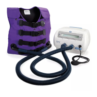
IV POLE SOCKETS
The Progressa® Bed comes with four standard IV sockets.
Two are located at the head end and two are located
behind the footboard at the corners of the foot end.
To help prevent injury and/or equipment damage, obey
these warnings:
• Warning—Remove all equipment from the foot-
end equipment sockets before you put the bed in
the chair position.
• Warning—Make sure there is sufficient room at
the head-end of the bed for equipment in the
sockets when you raise the bed or go in to the
Trendelendburg/Reverse Trendelenburg positions.
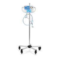
FRACTURE FRAME SOCKETS
To help prevent injury and/or equipment damage, obey these
warnings:
• Warning—Caregiver to evaluate patients for
entrapment and asphyxiation when using traction
equipment.
• Warning—Follow facility protocol for lockouts of bed
controls when traction equipment is installed.
There are four locations for the traction equipment to install—two at the head end, and one on each
side of the bed near the thigh section. Make sure to use the appropriate adapter for the traction
equipment according to the manufacturer’s instructions.
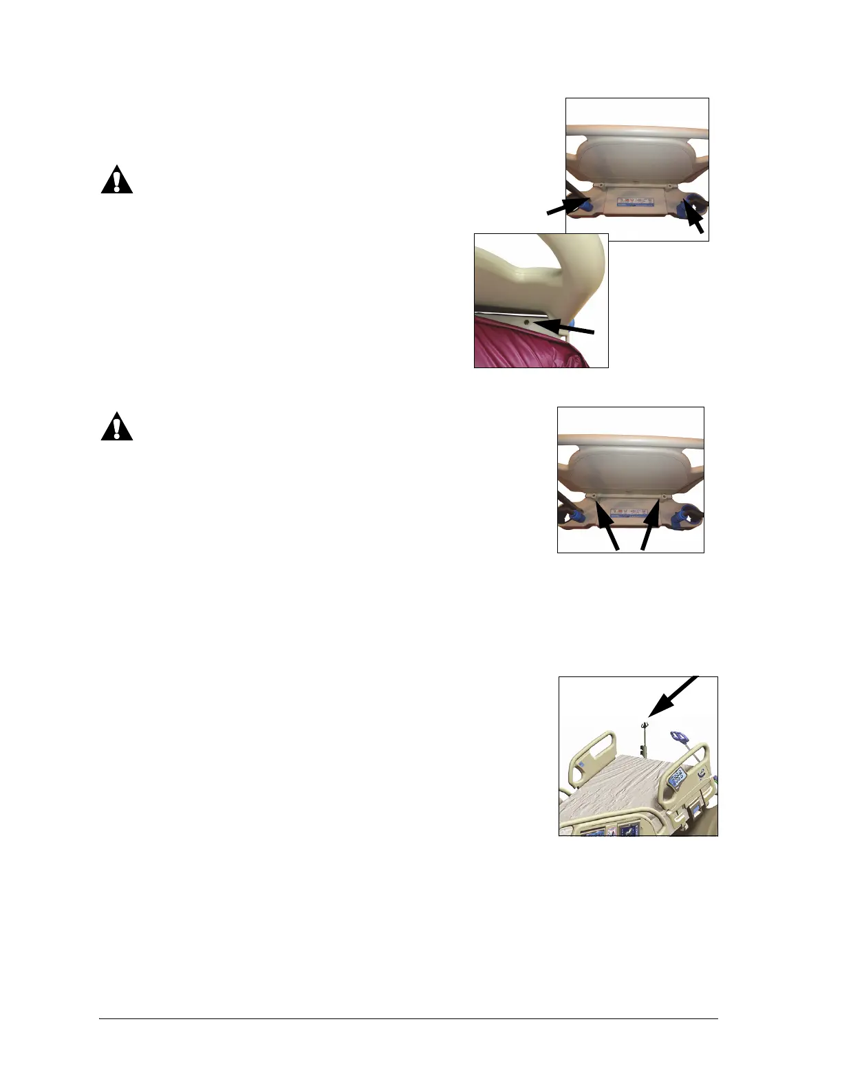
PERMANENT IV POLE OPTION
The Permanent IV Pole option consists of one IV pole that supports up to
two IV pumps plus bags. The IV pole is attached to the frame near one of
the corners of the headboard.
Up to 40 lb (18.1 kg) of total weight can be supported per pole.
A permanent IV pole will use one of the removable IV pole sockets on the
head-end of the bed.
To Raise
1. Lift the IV pole from its stored position from behind the headboard.
2. Make sure that the pole drops and locks into position.
3. Hold the bottom section.
4. Raise the middle and upper sections of the pole until they click and lock into place. The pole is ready
for use.