7.3.4.1 Function of DIP switches and rotary switches
? NOTE
• The mark “■” indicates the dip switches positions.
• No mark “■” indicates pin position is not affected.
• The gures show the settings before shipment or after selection.
• “Not used” means that the pin must not be changed. A malfunction might occur if changed.
! CAUTION
Before setting dip switches, rst turn the power supply OFF and then set the position of dip switches. If the switches are set without turning the power
supply OFF, the contents of the setting are invalid.
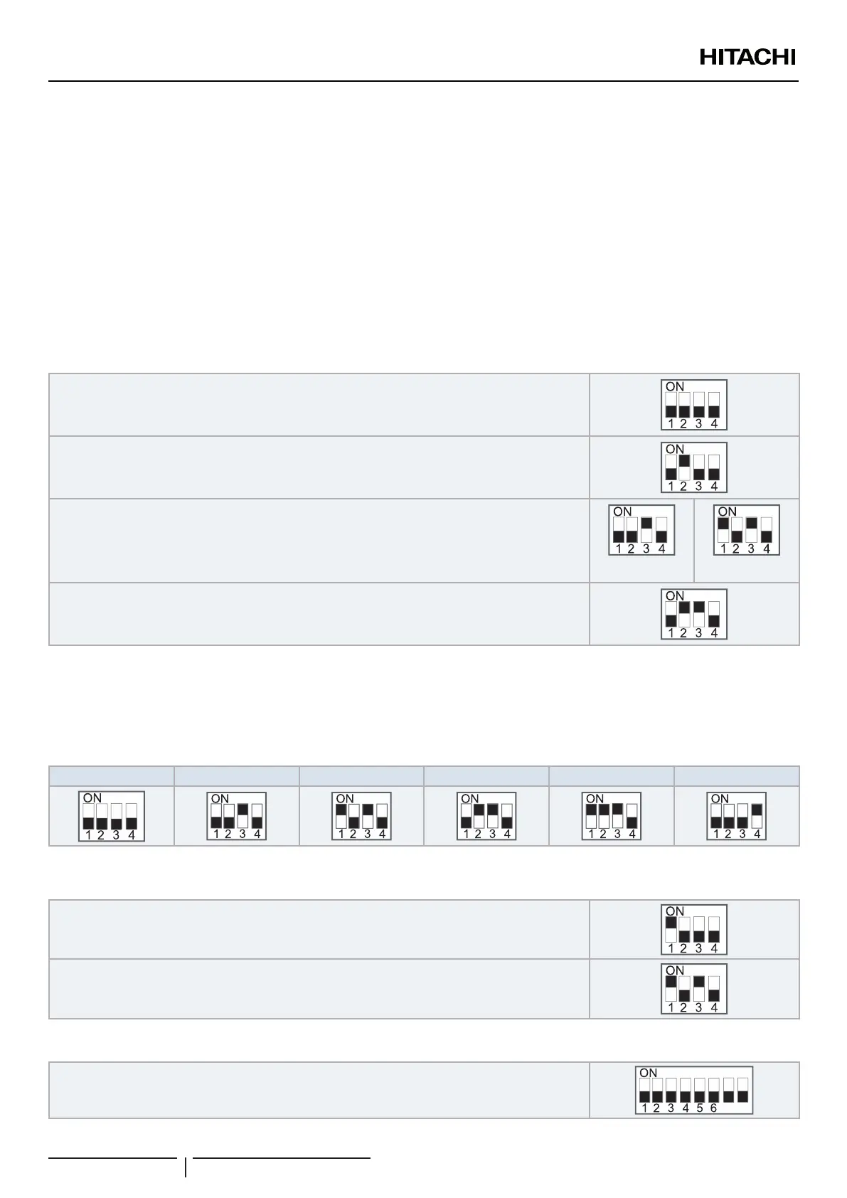
DSW1: Model setting
Setting is required in order to match with the model of the Sub YUTAKI installed.
YUTAKI S (*)
YUTAKI S COMBI (*)
YUTAKI S80
1~ 230V 50Hz 3N~ 400V 50Hz
YUTAKI M
? NOTE
(*): In case of installing the “Cooling kit” accessory, set the pin 4 of DSW1 to ON in order to enable the cooling operation.
DSW2: Unit capacity setting
Setting is required in order to match with the model of the Sub YUTAKI installed.
Factory setting 4.0HP 5.0HP 6.0HP 8.0HP 10.0HP
DSW3: Additional setting 1
Setting before shipment
1-step heater for 3-phase unit
DSW4: Additional setting 2
Setting before shipment
87
ELECTRICAL AND CONTROL SETTINGS
PMML0575 rev.2 - 03/2022
94
 Loading...