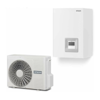
Circuit 1
Considerations:
• When demand on, inlet pipe is in orange, outlet in blue.
• When cooling, inlet pipe is in blue, outlet in orange. If thermo off, it is shown in gray.
• T
WO
shows value of T
WO3
in case there is buffer tank and T
WO3
sensor is used.
• Water pump 3 is shown when it is switched ON since there is buffer tank. Otherwise, water pump 1 is showed whenever it is
switched ON.
• Fan speed only shown when fan congured.
• T
room
& T
set
are only shown when available on operation information (exist wired or wireless thermostat for C1).
• The icon shown is dened on “Room icon” parameter under “controller settings”.
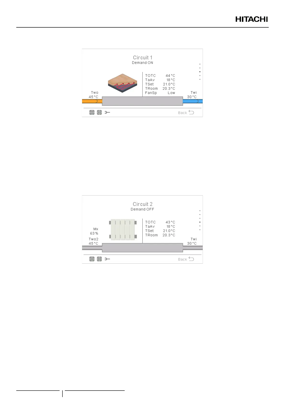
Circuit 2
Considerations:
• When demand on, inlet pipe is in orange, outlet in blue.
• When cooling, inlet pipe is in blue, outlet in orange. If thermo off, it is shown in gray.
• Water pump 2 is shown if used.
• Fan speed only shown when fan congured.
• T
room
& T
set
are only shown when available on operation information (exist wired or wireless thermostat for C1).
• The icon shown is dened on “Room icon” parameter under “Controller settings”.
UNIT CONTROLLER (PC-ARFH2E)
PMML0575 rev.2 - 03/2022
198
 Loading...