14
3.
Technical Description and Theory of Operation
3.1.
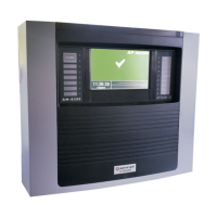
Overview of the ACM 150 monitor
The ACM 150 monitor can monitor any or all the following locations:
• Sources of a potential chemical leak, such as gas cabinets, valve boxes, pipes,
process equipment, semiconductor tools, and storage areas, to alert emergency
response teams of a pending problem and to shut off the flow of gases automatically.
• Plant emission ducts and stacks to determine the concentrations of various chemicals
released from the facility.
• Workplace areas to confirm that employees are not being exposed to chemicals and
to alert workers should a leak spread into their breathing zone.
The ACM 150 samples the air in these locations and analyzes it for many gaseous
chemicals. The samples are transferred to the ACM 150 monitor by 3/8-inch Teflon tubing
or polypropylene. An air filter is installed at or near the sample pick-up locations (tube
inlets) to keep the sample lines free of particles. As an option, a check valve can be added
after the filter to allow the line to be pressurized with air from the ACM 150. This enables
an automatic leak check of every sample tube once per day.
The ACM 150 monitor does not monitor all locations at once. It scans one area at a time
until all active areas have been monitored. It can scan as many as 40 sample areas.
3.2.
ACM 150 arrangement and assemblies
3.2.1. General arrangement
The ACM 150 monitor cabinet consists of these assemblies:
1. Main Power Switch
2. Sample Valve Manifolds
3. Sample Valve Control Panel
4. Touchscreen Computer Assembly
5. FTIR-Bench and Gas Cell Assembly
6. Pumps and Pump Cabinet
7. Cycle Valves and Cycle Valve Control Panel
8. Router
9. Relay Output Control Panel
10. Relay Outputs

 Loading...


