18
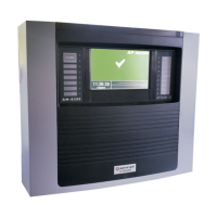
A column of LEDs on the left and right sides indicates the vacuum, measured in psi,
bypass flow (Bypass Vacuum), and sample flow (Sample Vacuum). They are a
troubleshooting aid should the vacuum fall below acceptable levels. Status LEDs are
provided for the following:
• Pump Enabled: The LEDs indicate adequate sample pump vacuum.
• Venturi: The LEDs indicate adequate venturi pump vacuum.
• Line Leak: This light illuminates when the ACM 150 monitor performs a Line Leak Test,
which may be initiated manually or automatically. To perform correctly, check valves
must be installed in the sample lines connected to the ACM 150 monitor for the Line
Leak Test to perform appropriately. This feature may be disabled via the configuration
software.
3.2.5. Control panel status
The three control panels on the ACM 150 monitor have the same Status LEDs. These
LEDs provide status on the following:
• Power On: Lights to confirm that power is supplied to the valves or relays associated
with the Control Panel. This LED should be lit whenever the ACM 150 monitor is
powered. Loss of power requires service attention.
• Test Mode: Lights when selecting the Manual Mode or Front panel Mode on the
touchscreen.
• Comm. Active: Flashes when the computer and the control panel communicate.
Frequent communication is expected.
Figure 8. Control Panel Status LEDs

 Loading...


