54
5.5.
Wiring the outputs
5.5.1. Access plates
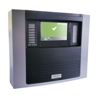
Figure 27 Shows two access plates on top of the ACM 150 monitor. They are provided for
wiring the outputs. Remove one or both plates and cut or drill, as necessary, to
accommodate your preferred connection, such as:
Mating to Wiremold or similar raceways
To connect to electrical conduit
Figure 27. Output Wiring Access Panels
5.5.2. Relay output wiring
All 86 relays on the Relay Output Board have plug-in connectors. Remove the connectors
and wire to them outside of the monitor. Then, plug them into the board. The connectors
have six terminals accommodating 18 AWG or smaller wires. The relays are numbered
on the board, which is shown in Figure 28.
5.5.2.1.
Standard output relays
There are 80 programmable relays. The default setup provides 40 Alarm 1 level and 40
Alarm 2 level outputs for up to 40 sample areas. Each relay is independently
programmable. The user can configure set points, sample areas, and gases in any
combination or grouping.
The Relay Output Board has six status relays. They activate when the ACM 150 monitor
detects service requests or malfunction incidents or when power is lost.

 Loading...


