6. Anyelectricalinterferenceinducedontothe4-20mAloopconductorsbytheinstallationmust
bekeptbelowthelevelsnecessarytocomplywiththegeneralrequirementsofEN50270.
In practice, this means that peak noise currents induced on the current loop should be no
greaterthan±0.25mA.
7. The0Vrailofthecontrolcard/systemisoftendirectlyconnectedtoonesideofthe4-20mA
current sensing resistor. Electrical noise on such a rail is therefore directly connected to the
4-20mAinput.Inordertoavoidadditionalnoisebeinginducedonthe0Vrail,itshouldnotbe
common with the safety earth/ground which frequently carries a high level of electrical noise.
8. The24Vsupplyshouldbefreefromlargetransientsanductuations.
ThetypeofcableusedforeldwiringbetweentheApextransmitterandcontrolequipment,and
between the Apex transmitter and Apex sensor if mounted remotely, should be selected to meet the
environmentalandhazardousarearequirements.Thecableinternalconstructionshouldbeaofthe
screened, multi-core, multi-stranded type. The terminals within the product will accept a maximum
conductorsizeof2.5mm
2
(14AWG).Therecommendedminimumconductorsizeis0.75mm
2
(20AWG).Theconductorsshouldbesizedtogiveatotalpowersupplyloopresistanceoflessthan
30Ohms(ECCcartridge)or160hms(Catalyticcartridge).
If remote mounting the sensor from the transmitter a 4-core, screened cable with a minimum
conductorsizeof0.75mm
2
(20AWG)isrequired.
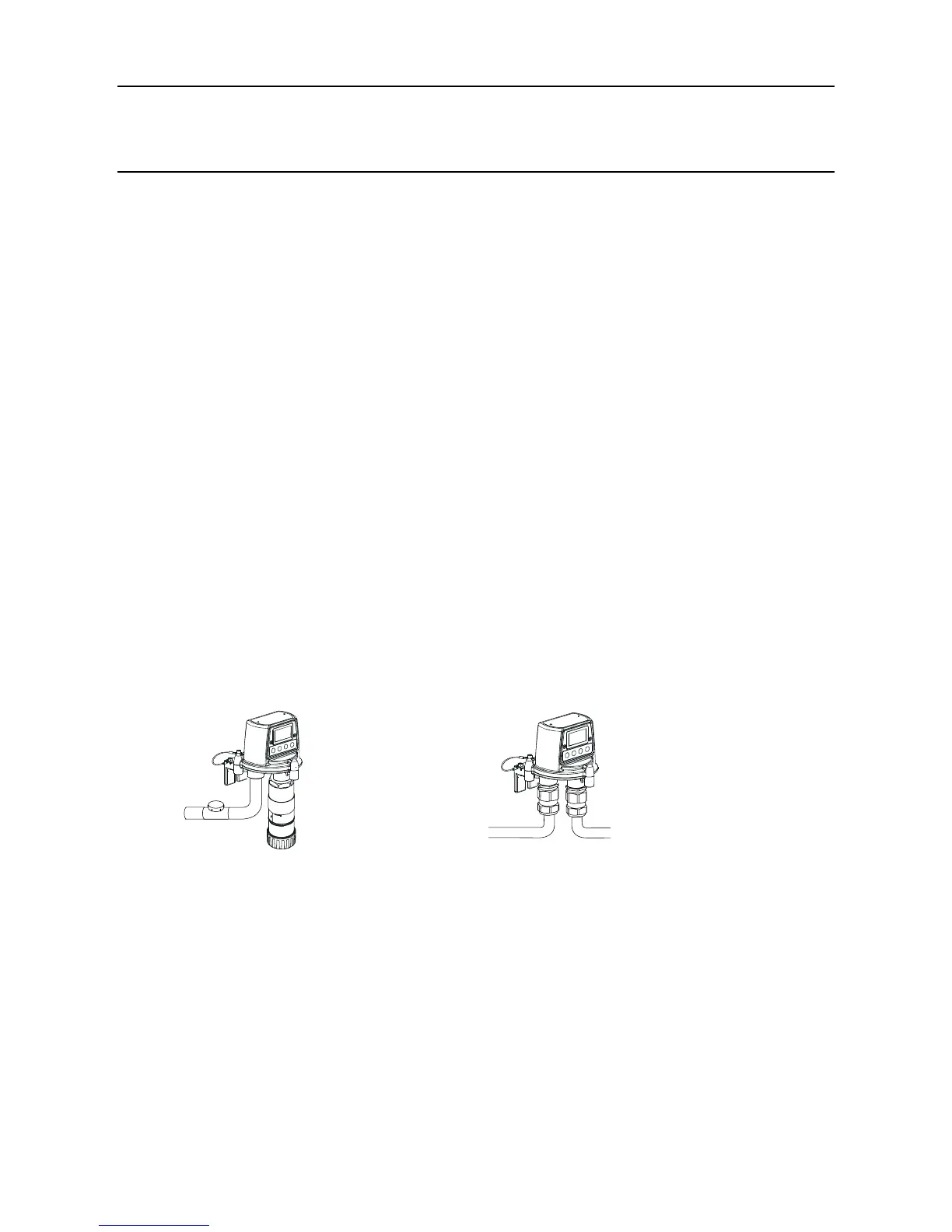
3.1 TRANSMITTER UNIT AND CERTIFIED SENSOR
ThisinstallationconsistsofaTransmitterUnitwithCertiedSensorlocallymountedatthe
TransmitterUnittogetherwitheldwiring.
Apex Transmitter Unit
with Certied Sensor
(North America-style
installation)
Apex Transmitter Unit
with Certied Sensor
(European-style
installation)
The system components can be installed by a single technician.
Thisproceduredescribeshowto:
• install a Transmitter Unit
• t a Certied Sensor to the local Transmitter Unit
• connect up the Certied Sensor and eld wiring
• congure the Transmitter Unit relay and alarm settings
• install a gas sensing cartridge into the Certied Sensor
Refer to the General Installation Guidelines at the beginning of this chapter.
3. INSTALLATION
 Loading...


