(14) RetthecaporaccessorytotheCertiedSensor.
Reverse the removal procedure.
(15) Check that the system is working correctly.
Use the Calibration Menu => Gas Challenge menu option to check correct operation of the
unit in the presence of the gas being sensed without triggering alarms, etc. (see Chapter 4).
Apply gas using a gas test module.
(16) Return the system to normal operation.
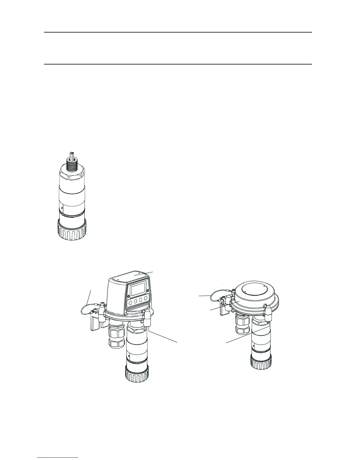
5.2.3 Changing the Certied Sensor
TheCertiedSensormaybemountedinaTransmitterUnitor
remotelyinaCertiedJunctionBox.Whenreplacing
certiedcomponentsalsorefertotheControlDrawings
(see Appendix B).
ToreplaceaCertiedSensorttedtoaTransmitterUnitora
CertiedJunctionBoxcarryoutthefollowingprocedure:
Caution: EnsurethattheTransmitterUnit/Certied
JunctionBoxamepathisnotdamagedduring
thisprocedure.Theamepathisformedbythe
matingsurfacesoftheTransmitterUnit/Certied
JunctionBoxtopandbase(seethecomponent
diagrams in Chapter 3).
(1) Isolate all associated power supplies and ensure that they remain OFF during this procedure.
Ensure a gas free atmosphere.
Transmitter Unit
top
Top fixing screw
(3 off)
o
Certified Junction
Box top
Metal
retaining
cable
Metal retaining
cable
(2) DetachtheTransmitterUnitorCertiedJunctionBoxtop.
Unscrew the three captive M8 hexagon key bolts underneath the base. Lift the top clear.
For the Transmitter Unit only lift the top clear of the locating pins.
5. MAINTENANCE

 Loading...


