5. MAINTENANCE
Caution: For the Transmitter Unit only take care not to damage or strain the ribbon cable
connectingthelidandtheInterconnectPCBinthebaseoftheunit.
(3) For the Transmitter Unit support the top and ensure that it is supported whilst the next two
steps are carried out.
FortheCertiedJunctionBoxletthemetalretainingcable,attachingthebaseandthetop,
hold the top, then go to Step (7).
(4) UnlatchtheribboncableZeroInsertionForce(ZIF)connectorontheTransmitterUnit
Interconnect PCB.
Grip the ends of the ZIF and pull it vertically upwards until it is felt to stop and the ribbon cable
is loose. Refer to the Transmitter Unit installation component diagrams in Chapter 3.
(5) Pull the ribbon cable clear.
(6) Remove the support from the Transmitter Unit top.
Let the metal retaining cable, attaching the base and the top, hold the top.
(7) DisconnecttheCertiedSensorwiring.
RemovethewiringfromtheterminalblocksontheInterconnectPCBinthebaseofthe
TransmitterUnitorCertiedJunctionBox.
Record the location of the sensor wiring in the terminal blocks.
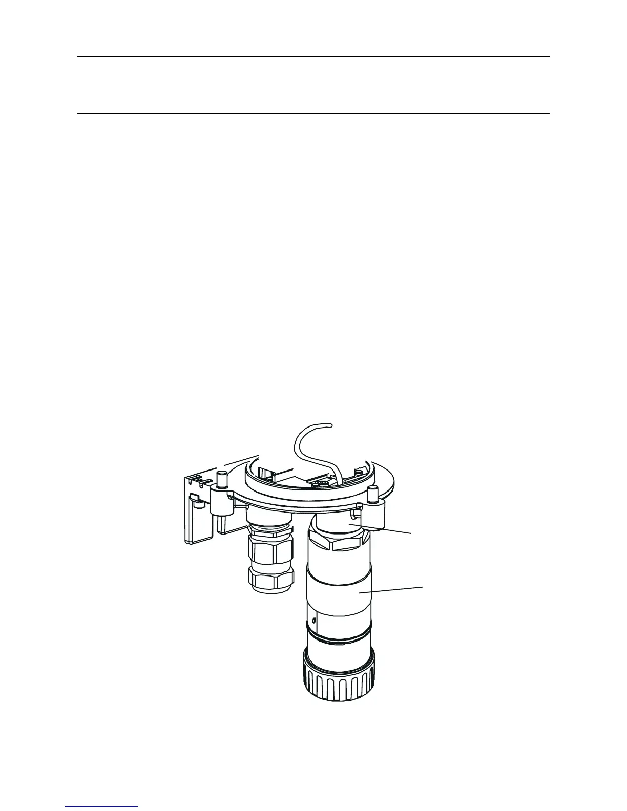
(8) UnscrewtheCertiedSensorfromitsmountingpoint.
Certified
Sensor

 Loading...


