5. MAINTENANCE
5.2.4 Changing the Transmitter Unit Front Panel Assembly
This assembly may need to be replaced if the screen becomes damaged or the display and buttons
donotoperatecorrectly.OneofthefollowingtwotypesofFrontPanelAssemblymaybetted
dependingontheTransmitterUnitversion:
• CSA Transmitter Unit Front Panel Assembly 2110B2825
• All other versions 2110B2820
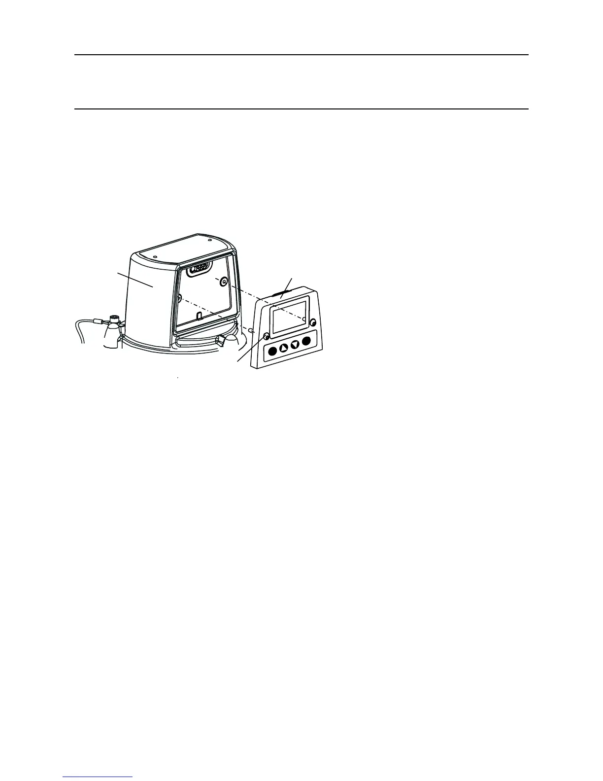
The assembly is attached to the top of the Transmitter Unit by two screws.
To replace the assembly carry out the following procedure.
(1) Isolate all associated power supplies and ensure that they remain OFF during this procedure.
Ensure a gas free atmosphere.
(2) Unscrew the two Front Panel Assembly retaining screws.
Use a hex-key tool to loosen the captive M4 screws.
(3) Pull the Front Panel Assembly forward away from the top.
TemporarilyrettheM4hex-keytooltooneoftheretainingscrewsandgentlyleverthe
assembly out of the recess in the top.
(4) Discard the removed Front Panel Assembly.
(5) Place the replacement assembly into the recess in the top of the Transmitter Unit.
(6) Secure the two retaining screws.
Tighten to 2.0Nm.
(7) Switch on all associated power supplies.
(8) Check that the system is working correctly.
Ensure that the LCD screen is displaying a valid Gas Reading (see Chapter 4). Carry out
a short random check of the menu system to ensure the front panel buttons are working
correctly and the Transmitter Unit is responding and the LCD Screen is showing the correct
information.
(9) Return the system to normal operation.
See Chapter 4.
esc
ok
Retaining screws
Apex top
Front Panel
Assembly

 Loading...


